HP ProLiant DL360p Gen8 Server User Guide Abstract This document is for the person who installs, administers, and troubleshoots servers and storage systems. HP assumes you are qualified in the servicing of computer equipment and trained in recognizing hazards in products with hazardous energy levels.
© Copyright 2012, 2014 Hewlett-Packard Development Company, L.P. The information contained herein is subject to change without notice. The only warranties for HP products and services are set forth in the express warranty statements accompanying such products and services. Nothing herein should be construed as constituting an additional warranty. HP shall not be liable for technical or editorial errors or omissions contained herein. Microsoft® and Windows® are U.S.
Contents Introduction .................................................................................................................................. 6 Server features .......................................................................................................................................... 6 Component identification ............................................................................................................... 7 Front panel components .....................................
Processor and fan module option .............................................................................................................. 35 Memory options ...................................................................................................................................... 42 HP SmartMemory .......................................................................................................................... 44 Memory subsystem architecture ..........................................
ROMPaq utility .............................................................................................................................. 87 Automatic Server Recovery ............................................................................................................. 87 USB support .................................................................................................................................. 87 Redundant ROM support ............................................................
Introduction Server features The HP ProLiant DL360p Gen8 SE Server comes with industry leading performance, efficiency, capacity, and reliability in a 1U space. The server provides enterprise-class design for performance workloads with versatile and future requirements, and it is ideal for low latency applications in a dense rack package. The HP ProLiant DL360p Gen8 SE Server is a space-conscious, 2-processor performance server with industry leading feature sets.
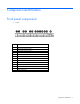
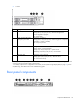
Component identification Front panel components • 8 SFF Item Description 1 SAS/SATA/SSD drive bay 1 2 SAS/SATA/SSD drive bay 2 3 SAS/SATA/SSD drive bay 3 4 SAS/SATA/SSD drive bay 4 5 SAS/SATA/SSD drive bay 5 6 SAS/SATA/SSD drive bay 6 7 SAS/SATA/SSD drive bay 7 8 Systems Insight Display 9 DVD-ROM drive (optional) 10 SAS/SATA/SSD drive bay 8 11 Front video connector (front video port adapter required) 12 USB connectors (2) 13 Serial number tab Component identification 7
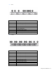
• 4 LFF Item Description 1 SAS/SATA/SSD drive bay 1 2 DVD-ROM drive (optional) 3 SAS/SATA/SSD drive bay 2 4 Serial number tab 5 SAS/SATA/SSD drive bay 3 6 Systems Insight Display 7 SAS/SATA/SSD drive bay 4 8 Front video connector (front video port adapter required) 9 USB connectors (2) • 10 SFF Item Description 1 SAS/SATA/SSD drive bay 1 2 SAS/SATA/SSD drive bay 2 3 SAS/SATA/SSD drive bay 3 4 SAS/SATA/SSD drive bay 4 5 SAS/SATA/SSD drive bay 5 6 SAS/SATA/SSD drive bay 6
Item Description 11 Systems Insight Display 12 USB connector Front panel LEDs and buttons • 8 SFF or 4 LFF Item Description Status 1 UID button/LED Solid blue = Activated Flashing blue (1 Hz/cycle per sec) = Remote management or firmware upgrade in progress Off = Deactivated 2 Power On/Standby button and system power LED Solid green = System on Flashing green (1 Hz/cycle per sec) = Performing power on sequence Solid amber = System in standby Off = No power present* 3 Health LED Solid gree
• 10 SFF Item Description Status 1 UID button/LED Solid blue = Activated Flashing blue (1 Hz/cycle per sec) = Remote management or firmware upgrade in progress Off = Deactivated 2 Power On/Standby button and system power LED Solid green = System on Flashing green (1 Hz/cycle per sec) = Performing power on sequence Solid amber = System in standby Off = No power present* 3 Health LED Solid green = Normal Flashing amber = System degraded Flashing red (1 Hz/cycle per sec) = System critical Fast-fla
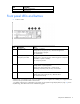
Item Description 1 Slot 2 PCIe 3.0 x16 (full height/half length) 2 FlexibleLOM ports (Shown: 4x1Gb / Optional: 2x10Gb) 3 Video connector 4 Serial connector 5 Slot 1 PCIe 3.0 x8 (low profile) 6 iLO management port 7 USB connectors (4) 8 Power supply bay 2 9 Power supply bay 1 Rear panel LEDs and buttons Item Description Status 1L HP iLO/standard NIC activity LED Solid green = Activity exists. Flashing green = Activity exists. Off = No activity exists.
Item Description Status • • • • 4 AC power unavailable Power supply failed Power supply in standby mode Power supply exceeded current limit Power supply 1 LED Solid green = Normal Off = One or more of the following conditions exists: • • • • AC power unavailable Power supply failed Power supply in standby mode Power supply exceeded current limit System board components Item Description 1 TPM connector 2 PCIe x8 riser connector 3 PCIe x16 riser connector 4 FlexibleLOM 5 SAS cache module c
Item Description 8 SAS connector B (Drives 5–8) 9 SAS connector A (drives 1–4) 10 NMI jumper 11 System maintenance switch 12 Processor 1 13 Fan module 8 connector 14 Processor 1 DIMM slots 15 Fan module 7 connector 16 Fan module 6 connector 17 Fan module 5 connector 18 Processor 1 DIMM slots 19 Fan module 4 connector 20 Processor 2 DIMM slots 21 Fan module 3 connector 22 Fan module 2 connector 23 Fan module 1 connector 24 Processor 2 DIMM slots 25 Processor 2 26 Drive
System maintenance switch Position Default Function S1 Off Off = HP iLO security is enabled. On = HP iLO security is disabled. S2 Off Off = System configuration can be changed. On = System configuration is locked. S3 Off Reserved S4 Off Reserved S5 Off Off = Power-on password is enabled. On = Power-on password is disabled. S6 Off Off = No function On = ROM reads system configuration as invalid.
Systems Insight Display LEDs The HP Systems Insight Display LEDs represent the system board layout. The display provides status for all internal LEDs and enables diagnosis with the access panel installed. To view the LEDs, access the HP Systems Insight Display (on page 21).
Systems Insight Display LED combinations When the health LED on the front panel illuminates either amber or red, the server is experiencing a health event. Combinations of illuminated Systems Insight Display LEDs, the system power LED, and the health LED indicate system status. Systems Insight Display Health LED LED and color Processor (amber) Red System power LED Status Amber One or more of the following conditions may exist: • • • • Processor in socket X has failed.
Device numbers • 4 LFF configuration • 8 SFF configuration • 10 SFF configuration IMPORTANT: A cache module is required for a 10 SFF drive cage. Drives installed in a 10 SFF configuration do not function without a cache module. For more information, see "Installing the cache module (on page 56)".
Hot-plug drive LED definitions Item LED Status 1 Locate Solid blue The drive is being identified by a host application. Flashing blue The drive carrier firmware is being updated or requires an update. Rotating green Drive activity Off No drive activity Solid white Do not remove the drive. Removing the drive causes one or more of the logical drives to fail. Off Removing the drive does not cause a logical drive to fail. Solid green The drive is a member of one or more logical drives.
When only one processor is installed, be sure the fan blanks are always installed in bays 1 and 2 to ensure proper cooling. • Two-processor configuration Install fans 1 and 2 only when processor 2 is installed. When only one processor is installed, always install the fan blanks.
Operations Power up the server To power up the server, press the Power On/Standby button. Power down the server Before powering down the server for any upgrade or maintenance procedures, perform a backup of critical server data and programs. IMPORTANT: When the server is in standby mode, auxiliary power is still being provided to the system. To power down the server, use one of the following methods: • Press and release the Power On/Standby button.
WARNING: To reduce the risk of personal injury, be careful when pressing the server rail-release latches and sliding the server into the rack. The sliding rails could pinch your fingers. 5. After performing the installation or maintenance procedure, slide the server into the rack: a. Slide the server fully into the rack. b. Secure the server by tightening the thumbscrews. 6. Connect the peripheral cables and power cords.
The display can be rotated up to 90 degrees.
The display can be rotated up to 90 degrees. Remove the access panel WARNING: To reduce the risk of personal injury from hot surfaces, allow the drives and the internal system components to cool before touching them. CAUTION: Do not operate the server for long periods with the access panel open or removed. Operating the server in this manner results in improper airflow and improper cooling that can lead to thermal damage. To remove the component: 1. Power down the server (on page 20). 2.
b. Disconnect each power cord from the server. 3. Extend the server from the rack (on page 20). 4. Remove the access panel (on page 23). 5. Disconnect the cable from the cache module or PCIe controller. 6. Remove the FBWC capacitor pack. Remove the PCI riser cage CAUTION: To prevent damage to the server or expansion boards, power down the server and remove all AC power cords before removing or installing the PCI riser cage. 1. Power down the server (on page 20). 2. Remove all power: a.
The server may look different than the one shown in the following illustration, depending on the server model. Install the PCI riser cage CAUTION: To prevent damage to the server or expansion boards, power down the server and remove all AC power cords before removing or installing the PCI riser cage. 1. Power down the server (on page 20). 2. Remove all power: a. Disconnect each power cord from the power source. b. Disconnect each power cord from the server. 3.
The server may look different than the one shown in the following illustration, depending on the server model. 8. Install the access panel (on page 23). 9. Slide the server into the rack. 10. Connect each power cord to the server. 11. Connect each power cord to the power source. 12. Power up the server (on page 20).
Setup Support and deployment services Delivered by experienced, certified engineers, HP Care Pack services help you keep your servers up and running with support packages tailored specifically for HP ProLiant systems. HP Care Packs let you integrate both hardware and software support into a single package. A number of service level options are available to meet your needs.
• Leave a minimum clearance of 63.5 cm (25 in) in front of the rack. • Leave a minimum clearance of 76.2 cm (30 in) behind the rack. • Leave a minimum clearance of 121.9 cm (48 in) from the back of the rack to the back of another rack or row of racks. HP servers draw in cool air through the front and expel warm air through the rear.
Power requirements Installation of this equipment must comply with local and regional electrical regulations governing the installation of information technology equipment by licensed electricians. This equipment is designed to operate in installations covered by NFPA 70, 1999 Edition (National Electric Code) and NFPA-75, 1992 (code for Protection of Electronic Computer/Data Processing Equipment).
WARNING: To reduce the risk of electric shock or energy hazards: • This equipment must be installed by trained service personnel, as defined by the NEC and IEC 60950-1, Second Edition, the standard for Safety of Information Technology Equipment. • Connect the equipment to a reliably grounded SELV source. An SELV source is a secondary circuit that is designed so normal and single fault conditions do not cause the voltages to exceed a safe level (60 V direct current).
WARNING: To reduce the risk of personal injury or damage to the equipment, be sure that: • • • • • The leveling jacks are extended to the floor. The full weight of the rack rests on the leveling jacks. The stabilizing feet are attached to the rack if it is a single-rack installation. The racks are coupled together in multiple-rack installations. Only one component is extended at a time. A rack may become unstable if more than one component is extended for any reason.
WARNING: This server is very heavy. To reduce the risk of personal injury or damage to the equipment: • Observe local occupational health and safety requirements and guidelines for manual material handling. • Get help to lift and stabilize the product during installation or removal, especially when the product is not fastened to the rails. HP recommends that a minimum of two people are required for all rack server installations.
4. Use the strain relief clip from the server hardware kit to secure the power cord. 5. Connect the power cord to the power source. Powering on and selecting boot options 1. Connect the Ethernet cable. 2. Press the Power On/Standby button. 3. During the initial boot: o To modify the server configuration ROM default settings, press F9 when prompted from the start up sequence to enter the RBSU. By default, RBSU runs in the English language.
Provisioning can configure the server and install an operating system, eliminating the need for SmartStart CDs and Smart Update Firmware DVDs. To install an operating system on the server with Intelligent Provisioning (local or remote): a. Connect the Ethernet cable between the network connector on the server and a network jack. b. Press the Power On/Standby button. c. During server POST, press the F10 key. d.
Hardware options installation Introduction If more than one option is being installed, read the installation instructions for all the hardware options and identify similar steps to streamline the installation process. WARNING: To reduce the risk of personal injury from hot surfaces, allow the drives and the internal system components to cool before touching them. CAUTION: To prevent damage to electrical components, properly ground the server before beginning any installation procedure.
6.
7. Open each of the processor locking levers in the order indicated, and then open the processor retaining bracket. 8. Remove the clear processor socket cover. Retain the processor socket cover for future use.
9. Install the processor. Verify that the processor is fully seated in the processor retaining bracket by visually inspecting the processor installation guides on either side of the processor. THE PINS ON THE SYSTEM BOARD ARE VERY FRAGILE AND EASILY DAMAGED. CAUTION: THE PINS ON THE SYSTEM BOARD ARE VERY FRAGILE AND EASILY DAMAGED. To avoid damage to the system board, do not touch the processor or the processor socket contacts. 10. Close the processor retaining bracket.
11. Press and hold the processor retaining bracket in place, and then close each processor locking lever. Press only in the area indicated on the processor retaining bracket. 12. Remove the thermal interface protective cover from the heatsink. 13.
o Caged heatsink o Screw-down heatsink Hardware options installation 40
14. Remove the fan blanks. 15. Install the fans: CAUTION: To avoid thermal shutdown, all fans must be installed in a dual processor configuration. o For fans with latches, do the following: a. Install the fans into slots 1 and 2.
b. Secure the locking latches. o For fans without latches, install the fans into slots 1 and 2. 16. Install the access panel (on page 23). 17. Slide the server into the rack. 18. Connect each power cord to the server. 19. Connect each power cord to the power source. 20. Power up the server (on page 20). Memory options IMPORTANT: This server does not support mixing LRDIMMs, RDIMMs, or UDIMMs.
• UDIMMs represent the most basic type of memory module and offer lower latency in one DIMM per channel configurations and (relatively) low power consumption, but are limited in capacity. • RDIMMs offer larger capacities than UDIMMs and include address parity protection. • LRDIMMs support higher densities than single- and dual-rank RDIMMs, and higher speeds than quad-rank RDIMMs. This support enables you to install more high capacity DIMMs, resulting in higher system capacities and higher bandwidth.
DIMM type DIMM rank 1 DIMM per channel 2 DIMMs per channel 3 DIMMs per channel RDIMM Dual-rank (8 GB) 1333 1333 1066 RDIMM Single-rank (8 GB) 1600 1600 1333 (E5-2000) 800 (E5-2600v2) RDIMM Single-rank (8 GB) 1866 1866 1066 4 RDIMM Dual-rank (16 GB) 1333 1333 1066 1 RDIMM Dual-rank (16 GB) 1600 1600 1333 (E5 2000) 800 (E5 2600v2) RDIMM Dual-rank (16 GB) 1866 LRDIMM 1333 UDIMM Quad-rank (32 GB) Quad-rank (32 GB) Dual-rank (8 GB) 1333 3 1333 3 — UDIMM Dual-rank (8 GB) 16
Channel Population order Slot number 2 B F J 9 8 7 3 C G K 1 2 3 4 D H L 4 5 6 For the location of the slot numbers, see "DIMM slot locations ("DIMM slots" on page 13)." This multi-channel architecture provides enhanced performance in Advanced ECC mode. This architecture also enables Lockstep and Online Spare Memory modes. DIMM slots in this server are identified by number and by letter. Letters identify the population order. Slot numbers indicate the DIMM slot ID for spare replacement.
DIMM identification To determine DIMM characteristics, use the label attached to the DIMM and the following illustration and table. Item Description Definition 1 Size — 2 Rank 1R = Single-rank 2R = Dual-rank 4R = Quad-rank 3 Data width x4 = 4-bit x8 = 8-bit 4 Voltage rating L = Low voltage (1.35v) U = Ultra low voltage (1.
• Online spare memory—provides protection against failing or degraded DIMMs. Certain memory is reserved as spare, and automatic failover to spare memory occurs when the system detects a DIMM that is degrading. This allows DIMMs that have a higher probability of receiving an uncorrectable memory error (which would result in system downtime) to be removed from operation. Advanced Memory Protection options are configured in RBSU.
Lockstep memory configuration Lockstep mode provides protection against multi-bit memory errors that occur on the same DRAM device. Lockstep mode can correct any single DRAM device failure on x4 and x8 DIMM types. The DIMMs in each channel must have identical HP part numbers. General DIMM slot population guidelines Observe the following guidelines for all AMP modes: • Install DIMMs only if the corresponding processor is installed.
o LRDIMMs are treated as dual-rank DIMMs. Lockstep Memory population guidelines For Lockstep memory mode configurations, observe the following guidelines: • Observe the general DIMM slot population guidelines. • DIMM configuration on all channels of a processor must be identical. • In multi-processor configurations, each processor must have a valid Lockstep Memory configuration. • In multi-processor configurations, each processor may have a different valid Lockstep Memory configuration.
6. Install the DIMM. 7. Install the access panel (on page 23). 8. Slide the server into the rack. 9. Connect each power cord to the server. 10. Connect each power cord to the power source. 11. Power up the server (on page 20). Use RBSU ("HP ROM-Based Setup Utility" on page 83) to configure the memory mode. For more information about LEDs and troubleshooting failed DIMMs, see "Systems Insight Display LED combinations (on page 16).
Removing the hard drive blank Remove the component as indicated. Installing a hot-plug hard drive The server can support 4 hard drives in an LFF configuration, or 8 or 10 hard drives in an SFF configuration. To install the component: 1. Remove the drive blank. 2. Prepare the drive.
3. Install the drive. 4. Determine the status of the drive from the drive LED definitions ("Hot-plug drive LED definitions" on page 18). DVD-ROM and DVD-RW drive option All configurations of this server, except the 10 SFF drive configuration, support the installation of a DVD-ROM drive or a DVD-RW drive. To install the component: 1. Power down the server (on page 20). 2. Remove all power: a. Disconnect each power cord from the power source. b. Disconnect each power cord from the server. 3.
5. Remove the bezel blank from the DVD-ROM bay. 6. For an SFF DVD drive, do the following: The server may look different than the one shown in the following illustrations, depending on the server model. a. Install the DVD drive using the screws from this kit and a T-10/T-15 Torx screwdriver.
b. Connect the cable to the rear of the drive and to the SATA DVD-ROM drive connector on the system board. c. 7. Clip the cable to the power supply air baffle when routing it along the edge of the system board.
a. Connect the cable to the rear of the DVD drive, and then route the cable through the DVD drive bay. b. Install the DVD drive. c. Route and connect the other end of the cable to the SATA DVD-ROM drive connector on the system board, using the same steps provided for the SFF DVD-ROM drive. 8. Install the access panel (on page 23). 9. Slide the server into the rack. 10. Connect each power cord to the server. 11. Connect each power cord to the power source. 12. Power up the server (on page 20).
Controller options The server ships with an embedded Smart Array P420i controller. For more information about the storage controller and its features, select the relevant controller user documentation on the HP website (http://www.hp.com/go/smartstorage/docs). To configure arrays, see the HP Smart Storage Administrator User Guide on the HP website (http://www.hp.com/go/smartstorage/docs). Upgrade options exist for the integrated array controller.
To install the component: 1. Power down the server (on page 20). 2. Remove all power: a. Disconnect each power cord from the power source. b. Disconnect each power cord from the server. 3. Extend the server from the rack (on page 20). 4. Remove the access panel (on page 23). 5. Remove the PCI riser cage (on page 24). 6. Install the cache module in the SAS cache module connector on the system board. For connector locations, see "System board components (on page 12)." 7.
CAUTION: When connecting or disconnecting the capacitor pack cable, the connectors on the cache module and cable are susceptible to damage. Avoid excessive force and use caution to avoid damage to these connectors. 7. Install the FBWC capacitor pack, and then connect the FBWC cable to the cache module. The second (left) capacitor pack cable connects to an optional Smart Array expansion board. 8. Install the PCI riser cage (on page 25). 9. Install the access panel (on page 23). 10.
2. Connect the front video adapter to the video device. To remove the front video adapter, squeeze the top and bottom together to release the locking mechanism. FlexibleLOM option WARNING: To reduce the risk of personal injury, electric shock, or damage to the equipment, remove the power cord to remove power from the server. The front panel Power On/Standby button does not completely shut off system power. Portions of the power supply and some internal circuitry remain active until AC power is removed.
3. Remove any attached network cables. 4. Extend the server from the rack (on page 20). 5. Remove the access panel (on page 23). 6. Loosen the thumbscrew. 7. Remove the existing FlexibleLOM. To replace the component: 1. Firmly seat the FlexibleLOM in the slot, and then tighten the thumbscrew. 2. Install the access panel (on page 23). 3. Slide the server into the rack. 4. Connect the LAN segment cables. 5. Connect each power cord to the server. 6.
7. Power up the server (on page 20). Expansion board option The server ships with PCIe riser boards and expansion slots. PCIe expansion boards are supported with optional riser boards. IMPORTANT: Be sure you are using a supported expansion board. For information on supported expansion boards, see the QuickSpecs on the HP website (http://www.hp.com/support). To install the component: 1. Power down the server (on page 20). 2. Remove all power: a. Disconnect each power cord from the power source. b.
Redundant hot-plug power supply option CAUTION: All power supplies installed in the server must have the same output power capacity. Verify that all power supplies have the same part number and label color. The system becomes unstable and may shut down when it detects mismatched power supplies.
3. Remove the protective cover from the connector pins on the power supply. WARNING: To reduce the risk of electric shock or damage to the equipment, do not connect the power cord to the power supply until the power supply is installed. 4. Install the redundant power supply into the bay until it clicks into place.
5. Connect the power cord to the power supply. 6. Route the power cord through the cable management solution. 7. Connect the power cord to the power source. 8. Be sure that the power supply LED is green ("Rear panel LEDs and buttons" on page 11). 48V DC power supply option One of the following optional HP input cables with pre-fastened ring tongues may be purchased from HP or an authorized reseller: • A5S97A—1.3-m (4.27-ft) 48V DC Power Cable Kit • A5S98A—2.5-m (8.
2. If you are not using an optional HP input cable, with the ground cable disconnected from the 48V power source, crimp the ring tongues to the power and ground cables coming from the 48V source. IMPORTANT: The power supply uses two power ring tongues and one ground ring tongue. They are not interchangeable. 3. Remove the safety cover from the terminal block on the front of the power supply. 4. Remove the screws from the terminal block.
5. Attach the ground (earthed) wire to the ground screw and washer and tighten to 1.47 N m (13 lb-in) of torque. The ground wire must be connected before the positive or negative lead wires.
6. Attach the power ring tongues to the terminal block, following the polarity label below the terminal block, and then tighten the screws to 1.47 N m (13 lb-in) of torque. 7. Replace the safety cover.
8. Insert the power supply into the power supply bay until it clicks into place. 9. Route the power cord. Use best practices when routing power cords and other cables. A cable management arm is available to help with routing. To obtain a cable management arm, contact an HP authorized reseller. 10. Make sure the 48V DC power source is off or the PDU breaker is in the off position, and then connect the power cord to the 48V DC power source or PDU. 11.
HP Trusted Platform Module option For more information about product features, specifications, options, configurations, and compatibility, see the product QuickSpecs on the HP Product Bulletin website (http://www.hp.com/go/productbulletin). Use these instructions to install and enable a TPM on a supported server. This procedure includes three sections: 1. Installing the Trusted Platform Module board (on page 69). 2. Retaining the recovery key/password (on page 71). 3.
a. Disconnect each power cord from the power source. b. Disconnect each power cord from the server. 3. Remove the server from the rack, if necessary ("Remove the server from the rack" on page 21). 4. Place the server on a flat, level work surface. 5. Remove the access panel (on page 23). 6. Remove the PCI riser cage (on page 24). CAUTION: Any attempt to remove an installed TPM from the system board breaks or disfigures the TPM security rivet.
11. Install the server into the rack ("Installing the server into the rack" on page 31). 12. Connect each power cord to the server. 13. Connect each power cord to the power source. 14. Power up the server (on page 20). Retaining the recovery key/password The recovery key/password is generated during BitLocker™ setup, and can be saved and printed after BitLocker™ is enabled. When using BitLocker™, always retain the recovery key/password.
Cabling Cabling overview This section provides guidelines that help you make informed decisions about cabling the server and hardware options to optimize performance. For information on cabling peripheral components, refer to the white paper on high-density deployment at the HP website (http://www.hp.com/products/servers/platforms). CAUTION: When routing cables, always be sure that the cables are not in a position where they can be pinched or crimped.
• LFF DVD-ROM and DVD-RW drive cabling The server may look different than the one shown in the following illustration, depending on the server model. Chipset SATA cable option With the chipset SATA cable option, the chipset SATA controller can be used with a single SATA hard drive that is installed in one hard drive bay of the SFF or LFF hard drive cage.
• o The optical bay is disabled because the chipset SATA controller port on the system board is redirected from the optical bay to the drive cage. o Hard drive status LEDs are not supported. o Hard drive thermal status monitoring is not supported. o Hot-plug operation is not supported. Because only one drive bay is enabled, all remaining drives can be removed. For proper thermal cooling, install blanks in all bays that do not have a drive installed. Order a sufficient number of 6.35-cm (2.
The server may look different than the one shown in the following illustrations, depending on the server model. 6. Disconnect the SATA cable from the optical drive and the SATA connector on the system board. The optical bay is disabled with the chipset SATA cable option. 7. Connect the chipset SATA cable: a. Connect the chipset SATA cable connector to the chipset SATA controller port on the system board.
b. Connect the remaining chipset SATA cable connector to the SATA header on the hard drive cage. 8. Clip the cable to the power supply air baffle when routing it along the edge of the system board. 9. Coil the cables behind the hard drive backplane to minimize airflow impact. 10. Install the access panel (on page 23). 11. Install the server into the rack ("Installing the server into the rack" on page 31). 12. Remove any installed hard drives. 13.
FBWC capacitor pack cabling The second (left) capacitor pack cable connects to an optional Smart Array expansion board.
Software and configuration utilities Server mode The software and configuration utilities presented in this section operate in online mode, offline mode, or in both modes.
HP iLO enables and manages the Active Health System (on page 79) and also features Agentless Management. All key internal subsystems are monitored by HP iLO. SNMP alerts are sent directly by HP iLO regardless of the host operating system or even if no host operating system is installed. HP Insight Remote Support software (on page 82) is also available in HP iLO with no operating system software, drivers, or agents.
The data that is collected is managed according to the HP Data Privacy policy. For more information see the HP website (http://www.hp.com/go/privacy). The Active Health System log, in conjunction with the system monitoring provided by Agentless Management or SNMP Pass-thru, provides continuous monitoring of hardware and configuration changes, system status, and service alerts for various server components. The Agentless Management Service is available in the SPP, which is a disk image (.
see the Resources tab on the HP website (http://www.hp.com/go/ilo). For consolidated drive and firmware update packages, see the HP Systems and Server Software Management page on the HP website (http://www.hp.com/go/SmartUpdate).
HP Insight Remote Support software HP strongly recommends that you register your device for remote support to enable enhanced delivery of your HP Warranty, HP Care Pack Service, or HP contractual support agreement.
To download HP SUM, see the HP website (http://www.hp.com/go/hpsum/download). To access the HP Smart Update Manager User Guide, see the HP SUM Information Library (http://www.hp.com/go/hpsum/documentation).
NOTE: The server may not support all the following examples. Drives installed Drives used RAID level 1 1 RAID 0 2 2 RAID 1 3, 4, 5, or 6 3, 4, 5, or 6 RAID 5 More than 6 0 None To change any ORCA default settings and override the auto-configuration process, press the F8 key when prompted. For more information on RBSU, see the HP ROM-Based Setup Utility User Guide on the Documentation CD or the HP RBSU Information Library (http://www.hp.com/go/rbsu/docs).
Warning: The serial number should ONLY be modified by qualified service personnel. This value should always match the serial number located on the chassis. 5. Press the Enter key to clear the warning. 6. Enter the serial number and press the Enter key. 7. Select Product ID. The following warning appears: Warning: The Product ID should ONLY be modified by qualified service personnel. This value should always match the Product ID located on the chassis. 8. Enter the product ID and press the Enter key.
• If an optional controller is installed, when the system recognizes the controller during POST, press F5. For optimum performance, the minimum display settings are 1024 × 768 resolution and 16-bit color. Servers running Microsoft® operating systems require one of the following supported browsers: • Internet Explorer 6.0 or later • Mozilla Firefox 2.0 or later For Linux servers, see the README.TXT file for additional browser and support information.
For more information about the storage controller and its features, select the relevant controller user documentation on the HP website (http://www.hp.com/go/smartstorage/docs). To configure arrays, see the HP Smart Storage Administrator User Guide on the HP website (http://www.hp.com/go/smartstorage/docs). ROMPaq utility The ROMPaq utility enables you to upgrade the system firmware (BIOS). To upgrade the firmware, insert a ROMPaq USB Key into an available USB port and boot the system.
NOTE: The server ships with the same version programmed on each side of the ROM. Safety and security benefits When you flash the system ROM, ROMPaq writes over the backup ROM and saves the current ROM as a backup, enabling you to switch easily to the alternate ROM version if the new ROM becomes corrupted for any reason. This feature protects the existing ROM version, even if you experience a power failure while flashing the ROM.
• VCRM manages the repository for SPP. Administrators can view the SPP contents or configure VCRM to automatically update the repository with internet downloads of the latest software and firmware from HP. • VCA compares installed software versions on the node with updates available in the VCRM managed repository. Administrators configure VCA to point to a repository managed by VCRM.
Troubleshooting Troubleshooting resources The HP ProLiant Gen8 Troubleshooting Guide, Volume I: Troubleshooting provides procedures for resolving common problems and comprehensive courses of action for fault isolation and identification, issue resolution, and software maintenance on ProLiant servers and server blades. To view the guide, select a language: • English (http://www.hp.com/support/ProLiant_TSG_v1_en) • French (http://www.hp.com/support/ProLiant_TSG_v1_fr) • Spanish (http://www.hp.
System battery If the server no longer automatically displays the correct date and time, you may need to replace the battery that provides power to the real-time clock. Under normal use, battery life is 5 to 10 years. WARNING: The computer contains an internal lithium manganese dioxide, a vanadium pentoxide, or an alkaline battery pack. A risk of fire and burns exists if the battery pack is not properly handled. To reduce the risk of personal injury: • • • • Do not attempt to recharge the battery.
To replace the component, reverse the removal procedure. For more information about battery replacement or proper disposal, contact an authorized reseller or an authorized service provider.
Regulatory information Safety and regulatory compliance For safety, environmental, and regulatory information, see Safety and Compliance Information for Server, Storage, Power, Networking, and Rack Products, available at the HP website (http://www.hp.com/support/Safety-Compliance-EnterpriseProducts). Belarus Kazakhstan Russia marking Manufacturer Hewlett-Packard Company, Address: 3000 Hanover Street, Palo Alto, California 94304, U.S.
Valid date formats include the following: • YWW, where Y indicates the year counting from within each new decade, with 2000 as the starting point. For example, 238: 2 for 2002 and 38 for the week of September 9. In addition, 2010 is indicated by 0, 2011 by 1, 2012 by 2, 2013 by 3, and so forth. • YYWW, where YY indicates the year, using a base year of 2000. For example, 0238: 02 for 2002 and 38 for the week of September 9.
Electrostatic discharge Preventing electrostatic discharge To prevent damaging the system, be aware of the precautions you need to follow when setting up the system or handling parts. A discharge of static electricity from a finger or other conductor may damage system boards or other static-sensitive devices. This type of damage may reduce the life expectancy of the device. To prevent electrostatic damage: • Avoid hand contact by transporting and storing products in static-safe containers.
Specifications Environmental specifications Specification Value Temperature range* — Operating 10°C to 35°C (50°F to 95°F) Non-operating -30°C to 60°C (-22°F to 140°F) Relative humidity (noncondensing) — Operating 10% to 90% 28°C (82.4°F), maximum wet bulb temperature Non-operating 5% to 95% 38.7°C (101.7°F), maximum wet bulb temperature * All temperature ratings shown are for sea level. An altitude derating of 1°C per 304.8 m (1.8°F per 1,000 ft) to 3048 m (10,000 ft) is applicable.
• HP 750W Common Slot Gold Hot Plug Power Supply (92% efficiency) (on page 99) • HP 750W Common Slot Platinum Plus Hot Plug Power Supply (94% efficiency) (on page 100) • HP 750W Common Slot -48VDC Hot Plug Power Supply (94% efficiency) (on page 101) • HP 1200W Common Slot Platinum Plus Hot Plug Power Supply (94% efficiency) (on page 102) For detailed power supply specifications, see the quickspecs on the HP website (http://h18000.www1.hp.com/products/quickspecs/14209_div/14209_div.html).
Rated steady-state power 460 W at 100V to 120V AC input 460 W at 200V to 240V AC input Maximum peak power 460 W at 100V to 120V AC input 460 W at 200V to 240V AC input HP 460W Common Slot Platinum Plus Hot Plug Power Supply (94% efficiency) Specification Value Input requirements Rated input voltage 100 to 120 VAC, 200 to 240 VAC Rated input frequency 50 Hz to 60 Hz Rated input current 5.2 A at 100 VAC 2.
HP 750W Common Slot 277VAC Hot Plug Power Supply (94% efficiency) Specification Value Input requirements Rated input voltage 200 V to 277 V AC Rated input frequency 50 Hz–60 Hz Rated input current 4.1 A at 200 V AC 3.
Rated input voltage 100 to 120 VAC, 200 to 240 VAC Rated input frequency 50 Hz to 60 Hz Rated input current 8.9 A at 100 VAC 4.
4.
DC source and the point of connection of the earthing electrode conductor. CAUTION: To reduce the risk of electric shock or energy hazards: • This equipment must be installed by trained service personnel, as defined by the NEC and IEC 60950-1, Second Edition, the standard for Safety of Information Technology Equipment. • Connect the equipment to a reliably grounded SELV source.
Support and other resources Before you contact HP Be sure to have the following information available before you call HP: • Active Health System log (HP ProLiant Gen8 or later products) Download and have available an Active Health System log for 3 days before the failure was detected. For more information, see the HP iLO 4 User Guide or HP Intelligent Provisioning User Guide on the HP website (http://www.hp.com/go/ilo/docs).
providers or service partners) identifies that the repair can be accomplished by the use of a CSR part, HP will ship that part directly to you for replacement. There are two categories of CSR parts: • Mandatory—Parts for which customer self repair is mandatory. If you request HP to replace these parts, you will be charged for the travel and labor costs of this service. • Optional—Parts for which customer self repair is optional. These parts are also designed for customer self repair.
Pour plus d'informations sur le programme CSR de HP, contactez votre Mainteneur Agrée local. Pour plus d'informations sur ce programme en Amérique du Nord, consultez le site Web HP (http://www.hp.com/go/selfrepair). Riparazione da parte del cliente Per abbreviare i tempi di riparazione e garantire una maggiore flessibilità nella sostituzione di parti difettose, i prodotti HP sono realizzati con numerosi componenti che possono essere riparati direttamente dal cliente (CSR, Customer Self Repair).
HINWEIS: Einige Teile sind nicht für Customer Self Repair ausgelegt. Um den Garantieanspruch des Kunden zu erfüllen, muss das Teil von einem HP Servicepartner ersetzt werden. Im illustrierten Teilekatalog sind diese Teile mit „No“ bzw. „Nein“ gekennzeichnet. CSR-Teile werden abhängig von der Verfügbarkeit und vom Lieferziel am folgenden Geschäftstag geliefert. Für bestimmte Standorte ist eine Lieferung am selben Tag oder innerhalb von vier Stunden gegen einen Aufpreis verfügbar.
sustituciones que lleve a cabo el cliente, HP se hará cargo de todos los gastos de envío y devolución de componentes y escogerá la empresa de transporte que se utilice para dicho servicio. Para obtener más información acerca del programa de Reparaciones del propio cliente de HP, póngase en contacto con su proveedor de servicios local. Si está interesado en el programa para Norteamérica, visite la página web de HP siguiente (http://www.hp.com/go/selfrepair).
Opcional – Peças cujo reparo feito pelo cliente é opcional. Essas peças também são projetadas para o reparo feito pelo cliente. No entanto, se desejar que a HP as substitua, pode haver ou não a cobrança de taxa adicional, dependendo do tipo de serviço de garantia destinado ao produto. OBSERVAÇÃO: Algumas peças da HP não são projetadas para o reparo feito pelo cliente. A fim de cumprir a garantia do cliente, a HP exige que um técnico autorizado substitua a peça.
Support and other resources 109
Support and other resources 110
Acronyms and abbreviations ABEND abnormal end ACU Array Configuration Utility AMP Advanced Memory Protection ASR Automatic Server Recovery CSR Customer Self Repair FBWC flash-backed write cache HDIMM HyperCloud DIMM HP SIM HP Systems Insight Manager HP SUM HP Smart Update Manager IEC International Electrotechnical Commission iLO Integrated Lights-Out IML Integrated Management Log Acronyms and abbreviations 111
LFF large form factor LRDIMM load reduced dual in-line memory module NMI nonmaskable interrupt NVRAM nonvolatile memory ORCA Option ROM Configuration for Arrays PCIe Peripheral Component Interconnect Express PDU power distribution unit POST Power-On Self Test RBSU ROM-Based Setup Utility RDIMM registered dual in-line memory module RDP Rapid Deployment Pack SAS serial attached SCSI SATA serial ATA SD Secure Digital Acronyms and abbreviations 112
SELV separated extra low voltage SFF small form factor SSA HP Smart Storage Administrator TMRA recommended ambient operating temperature TPM Trusted Platform Module UDIMM unregistered dual in-line memory module UID unit identification VCA Version Control Agent VCRM Version Control Repository Manager Acronyms and abbreviations 113
Documentation feedback HP is committed to providing documentation that meets your needs. To help us improve the documentation, send any errors, suggestions, or comments to Documentation Feedback (mailto:docsfeedback@hp.com). Include the document title and part number, version number, or the URL when submitting your feedback.
Index A D AC power supply 97, 98, 99, 100, 102 access panel 23 Active Health System 78, 79 ACU (Array Configuration Utility) 78, 85, 86 Advanced ECC memory 47, 48, 84 airflow requirements 27, 28 AMP (Advanced Memory Protection) 84 AMP modes 84 Array Configuration Utility (ACU) 85, 86 ASR (Automatic Server Recovery) 87 authorized reseller 103 auto-configuration process 83 Automatic Server Recovery (ASR) 87 DC power supply 29, 64 Declaration of Conformity 93, 94 default settings 47 diagnosing problems 90 d
front panel components 7 front panel LEDs 9 front video adapter 58 G grounding methods 95 grounding requirements 29 H hard drive backplane cabling 72 hard drive bays 7 hard drive blanks 51 hard drive LEDs 18 hard drives, determining status of 18 hardware options 35 hardware options installation 31, 35 health driver 87 health LEDs 9 help resources 103 hot-plug power supply calculations 102 HP contact information 103 HP Insight Diagnostics 81 HP Insight Diagnostics survey functionality 81 HP Insight Remote
power supply bays 10 power supply LEDs 15 power supply specifications 97, 98, 99, 100, 101, 102 powering down 20 powering up 20 preparation procedures 20 problem diagnosis 90 Q QuickSpecs 78 R rack bezel 68 rack installation 27, 30, 31 rack mounting hardware 31 rack warnings 30 rack, removing server from 21 RBSU (ROM-Based Setup Utility) 78, 83, 84 RBSU configuration 83 rear panel buttons 11 rear panel components 10 rear panel LEDs 11 recommended ambient operating temperature (TMRA) 28 recovery key 71 red
USB support 87 utilities 78, 85 utilities, deployment 78, 82, 83 V ventilation 27 Version Control Agent (VCA) 88 Version Control Repository Manager (VCRM) 88 video connector 7, 10 W warnings 30 website, HP 103 Index 118