HP ProLiant DL360 G7 Server User Guide Abstract This document is for the person who installs, administers, and troubleshoots servers and storage systems. HP assumes you are qualified in the servicing of computer equipment and trained in recognizing hazards in products with hazardous energy levels.
© Copyright 2010, 2011 Hewlett-Packard Development Company, L.P. The information contained herein is subject to change without notice. The only warranties for HP products and services are set forth in the express warranty statements accompanying such products and services. Nothing herein should be construed as constituting an additional warranty. HP shall not be liable for technical or editorial errors or omissions contained herein. Microsoft and Windows are U.S.
Contents Component identification ............................................................................................................... 7 Front panel components ............................................................................................................................. 7 Front panel LEDs and buttons ...................................................................................................................... 8 Rear panel components .........................................
Processor and fan module option .............................................................................................................. 32 Memory options ...................................................................................................................................... 37 Memory subsystem architecture ....................................................................................................... 38 Single-, dual-, and quad-rank DIMMs ........................................
Integrated Management Log ........................................................................................................... 80 Remote support and analysis tools ............................................................................................................. 80 HP Insight Remote Support software ................................................................................................. 80 Keeping the system current .................................................................
Electrostatic discharge ............................................................................................................... 109 Preventing electrostatic discharge ............................................................................................................ 109 Grounding methods to prevent electrostatic discharge ................................................................................ 109 Specifications ......................................................................
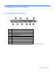
Component identification Front panel components Item Description 1 Hard drive bay 5 (optional)* 2 Hard drive bay 6 (optional)* 3 DVD tray/hard drive bays 7 and 8 (optional)* 4 HP Systems Insight Display 5 Front USB connector 6 Video connector 7 Hard drive bay 4 8 Hard drive bay 3 9 Hard drive bay 2 10 Hard drive bay 1 *An optional hard drive backplane is required when the server is configured with eight hard drives.
Front panel LEDs and buttons Item Description Status 1 UID LED/button Blue = Identification is activated. Flashing blue = System is being managed remotely. Off = Identification is deactivated. 2 Health LED Green = System health is normal. Amber = System health is degraded. To identify the component in a degraded state, see "Systems Insight Display LEDs (on page 13)". Red = System health is critical. To identify the component in a critical state, see "Systems Insight Display LEDs (on page 13)".
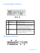
Item Description 1 Slot 1 PCIe2 x8 (8, 4, 2, 1) 2 Slot 2 PCIe2 x16 (16, 8, 4, 2, 1), 75W +EXT 75W* 3 Power supply bay 1 (populated) 4 Power supply bay 2 5 iLO 3 connector 6 Serial connector 7 Video connector 8 NIC 4 connector 9 NIC 3 connector 10 NIC 2 connector 11 NIC 1 connector 12 USB connectors (2) *This expansion slot provides 75 W of power to an adapter, with an additional 75 W of power supplied by external power.
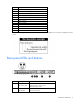
Item Description Status 3 iLO 3 NIC activity LED Green = Activity exists. Flashing green = Activity exists. Off = No activity exists. 4 iLO 3 NIC link LED Green = Link exists. Off = No link exists. 5 UID button/LED Blue = Identification is activated. Flashing blue = System is being managed remotely. Off = Identification is deactivated.
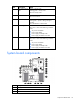
Item Description 4 SATA DVD-ROM drive connector 5 SAS cache module connector 6 Power button connector 7 Hard drive data connector 1 (drives 1–4) 8 Hard drive data connector 2 (drives 5–8) 9 Processor 1 DIMM slots (9) 10 Fan module 4 connector 11 Processor socket 1 (populated) 12 Fan module 3 connector 13 Fan module 2 connector 14 Processor socket 2 15 Fan module 1 connector 16 Processor 2 DIMM slots (9) 17 SD card slot 18 Internal USB connector 19 Hard drive power connector
DIMM slots DIMM slots are numbered sequentially (1 through 9) for each processor. The supported AMP modes use the letter assignments for population guidelines. System maintenance switch Position Default Function S1 Off Off = iLO 3 security is enabled. On = iLO 3 security is disabled. S2 Off Off = System configuration can be changed. On = System configuration is locked. S3 Off Reserved S4 Off Reserved S5 Off Off = Power-on password is enabled. On = Power-on password is disabled.
NMI jumper The NMI jumper allows administrators to perform a memory dump before performing a hard reset. Crash dump analysis is an essential part of eliminating reliability problems, such as hangs or crashes in OSs, device drivers, and applications. Many crashes can freeze a system, requiring you to do a hard reset. Resetting the system erases any information that would support root cause analysis. Systems running Microsoft® Windows® experience a blue-screen trap when the OS crashes.
Item Description Status For possible failure causes, see "Systems Insight Display LED combinations (on page 14)." Systems Insight Display LED combinations When the health LED on the front panel illuminates either amber or red, the server is experiencing a health event. Combinations of illuminated Systems Insight Display LEDs, the system power LED, and the health LED indicate system status.
Systems Insight Display Health LED LED and color Power cap (green) — System power LED Status Green Power is available. IMPORTANT: If more than one DIMM slot LED is illuminated, further troubleshooting is required. Test each bank of DIMMs by removing all other DIMMs. Isolate the failed DIMM by replacing each DIMM in a bank with a known working DIMM.
SAS and SATA hard drive LEDs Item Description 1 Fault/UID LED (amber/blue) 2 Online LED (green) Fan modules • One-processor configuration When only one processor is installed, be sure the fan blank is always installed to ensure proper cooling.
Install fan 2 only when processor 2 is installed. When only one processor is installed, always install the fan blank. Item Description 1 Fan module 1 2 Fan module 2 3 Fan module 3 4 Fan module 4 T-10/T-15 Torx screwdriver The server includes a T-10/T-15 Torx screwdriver that ships on the air baffle. Use the screwdriver to loosen screws or thumbscrews, as needed, during procedures.
Operations Power up the server To power up the server, press the Power On/Standby button. Power down the server WARNING: To reduce the risk of personal injury, electric shock, or damage to the equipment, remove the power cord to remove power from the server. The front panel Power On/Standby button does not completely shut off system power. Portions of the power supply and some internal circuitry remain active until AC power is removed.
5. After performing the installation or maintenance procedure, slide the server into the rack: a. Slide the server fully into the rack. b. Secure the server by tightening the thumbscrews. 6. Connect the peripheral cables and power cords. Access the HP Systems Insight Display To eject the HP Systems Insight Display: 1. Press and release the display. 2. Extend the display from the chassis. The display can be rotated up to 90 degrees.
Remove the access panel WARNING: To reduce the risk of personal injury from hot surfaces, allow the drives and the internal system components to cool before touching them. CAUTION: Do not operate the server for long periods with the access panel open or removed. Operating the server in this manner results in improper airflow and improper cooling that can lead to thermal damage. To remove the component: 1. Power down the server (on page 18). 2. Extend the server from the rack (on page 18). 3.
4. Remove the BBWC battery pack or the FBWC capacitor pack. Remove the air baffle 1. Power down the server (on page 18). 2. Extend the server from the rack (on page 18). 3. Remove the access panel (on page 20). 4. If installed, remove the BBWC battery pack or the FBWC capacitor pack (on page 20). 5. Remove the air baffle.
CAUTION: For proper cooling do not operate the server without the access panel, baffles, expansion slot covers, or blanks installed. If the server supports hot-plug components, minimize the amount of time the access panel is open. 1. Install the air baffle. 2. If removed, install the BBWC battery pack or the FBWC capacitor pack ("Installing the BBWC battery pack or the FBWC capacitor pack" on page 57). 3. Install the access panel (on page 20). 4. Slide the server into the rack. 5.
c. Lift the assembly to unseat the PCI riser boards, and then remove the assembly. Install the PCI riser board assembly CAUTION: To prevent damage to the server or expansion boards, power down the server and remove all AC power cords before removing or installing the PCI riser board assembly. 1. Align the PCI riser boards with the corresponding connectors on the system board, and then install the assembly. 2. Tighten the four PCI riser board assembly thumbscrews. 3.
6. Slide the server into the rack. 7. Power up the server (on page 18).
Setup Optional installation services Delivered by experienced, certified engineers, HP Care Pack services help you keep your servers up and running with support packages tailored specifically for HP ProLiant systems. HP Care Packs let you integrate both hardware and software support into a single package. A number of service level options are available to meet your needs.
Optimum environment When installing the server in a rack, select a location that meets the environmental standards described in this section. Space and airflow requirements To allow for servicing and adequate airflow, observe the following space and airflow requirements when deciding where to install a rack: • Leave a minimum clearance of 63.5 cm (25 in) in front of the rack. • Leave a minimum clearance of 76.2 cm (30 in) behind the rack. • Leave a minimum clearance of 121.
The maximum recommended ambient operating temperature (TMRA) for most server products is 35°C (95°F). The temperature in the room where the rack is located must not exceed 35°C (95°F). CAUTION: To reduce the risk of damage to the equipment when installing third-party options: • Do not permit optional equipment to impede airflow around the server or to increase the internal rack temperature beyond the maximum allowable limits. • Do not exceed the manufacturer’s TMRA.
includes a nondetachable cord that is wired to an industrial-style plug. NEMA locking-style plugs or those complying with IEC 60309 are considered suitable for this purpose. Using common power outlet strips for the server is not recommended. Rack warnings WARNING: To reduce the risk of personal injury or damage to the equipment, be sure that: • • • • • The leveling jacks are extended to the floor. The full weight of the rack rests on the leveling jacks.
Installing the server into the rack To install the server into a rack with square, round, or threaded holes, refer to the instructions that ship with the rack hardware kit. If you are installing the server into a telco rack, order the appropriate option kit at the RackSolutions.com website (http://www.racksolutions.com/hp). Follow the server-specific instructions on the website to install the rack brackets. Use the following information when connecting peripheral cables and power cords to the server.
Item Description 10 NIC 2 connector 11 NIC 1 connector 12 USB connectors (2) *This expansion slot provides 75 W of power to an adapter, with an additional 75 W of power supplied by external power. 3. Connect the power cord to the server. 4. Use the strain relief clip from the server hardware kit to secure the power cord. 5. Connect the power cord to the power source. Powering up and configuring the server To power up the server, press the Power On/Standby button.
• SmartStart assisted installation—Insert the SmartStart CD into the CD-ROM drive and reboot the server. • Manual installation—Insert the operating system CD into the CD-ROM drive and reboot the server. This process may require you to obtain additional drivers from the HP website (http://www.hp.com/support). Follow the on-screen instructions to begin the installation process.
Hardware options installation Introduction If more than one option is being installed, read the installation instructions for all the hardware options and identify similar steps to streamline the installation process. WARNING: To reduce the risk of personal injury from hot surfaces, allow the drives and the internal system components to cool before touching them. CAUTION: To prevent damage to electrical components, properly ground the server before beginning any installation procedure.
7. Remove the fan blank. 8. Install fan modules 3 and 4. CAUTION: Failure to completely open the processor locking lever prevents the processor from seating during installation, leading to hardware damage.
9. Open the processor locking lever and the processor socket retaining bracket. Do not remove the processor socket cover. IMPORTANT: Be sure the processor remains inside the processor installation tool. 10. If the processor has separated from the installation tool, carefully re-insert the processor in the tool. Handle the processor by the edges only, and do not touch the bottom of the processor, especially the contact area.
11. Align the processor installation tool with the socket, and then install the processor. THE PINS ON THE SYSTEM BOARD ARE VERY FRAGILE AND EASILY DAMAGED. CAUTION: THE PINS ON THE SYSTEM BOARD ARE VERY FRAGILE AND EASILY DAMAGED. To avoid damage to the system board: • Never install or remove a processor without using the processor installation tool. • Do not touch the processor socket contacts. • Do not tilt or slide the processor when lowering the processor into the socket.
12. Press the tabs on the processor installation tool to separate it from the processor, and then remove the tool. 13. Close the processor socket retaining bracket and the processor locking lever. The processor socket cover is automatically ejected. Remove the cover. CAUTION: Be sure to close the processor socket retaining bracket before closing the processor locking lever. The lever should close without resistance.
14. Remove the thermal interface media protective cover. 15. Install the heatsink. 16. Install the air baffle (on page 21). 17. If removed, install the BBWC battery pack or the FBWC capacitor pack ("Installing the BBWC battery pack or the FBWC capacitor pack" on page 57). 18. Install the access panel (on page 20). 19. Slide the server into the rack. 20. Power up the server (on page 18). Memory options IMPORTANT: This server does not support mixing RDIMMs and UDIMMs.
The memory subsystem in this server can support RDIMMs or UDIMMs. Both types are referred to as DIMMs when the information applies to both types. When specified as RDIMM or UDIMM, the information applies to that type only. All memory installed in the server must be the same type.
IMPORTANT: This server does not support mixing RDIMMs and UDIMMs. Attempting to mix these two types causes the server to halt during BIOS initialization. The memory subsystem may be populated with either RDIMMs or UDIMMs, but mixing the two types is not supported. To determine DIMM characteristics, use the label attached to the DIMM and the following illustration and table.
higher probability of receiving an uncorrectable memory error (which would result in system downtime) to be removed from operation. • Mirrored Memory—provides maximum protection against failed DIMMs. Uncorrectable errors in one channel are corrected by the mirror channel. Advanced Memory Protection options are configured in RBSU. If the requested AMP mode is not supported by the installed DIMM configuration, the server boots in Advanced ECC mode.
Online spare memory protection dedicates one rank of each memory channel for use as spare memory. The remaining ranks are available for OS and application use. If correctable memory errors occur at a rate higher than a specific threshold on any of the non-spare ranks, the server automatically copies the memory contents of the degraded rank to the online spare rank. The server then deactivates the failing rank and automatically switches over to the online spare rank.
• UDIMM: A through F, sequentially in alphabetical order. Do not populate DIMM slots G through I. Multi-processor Advanced ECC population order For Advanced ECC mode configurations with multiple processors, populate the DIMM slots for each processor in the following order: • RDIMM: Sequentially in alphabetical order (A through I) • UDIMM: A through F, sequentially in alphabetical order. Do not populate DIMM slots G through I.
• o Last: G and H o Do not populate slots C, F, or I. UDIMM o First: A and B o Last: D and E o Do not populate slots C, F, G, H, or I. After installing the DIMMs, use RBSU to configure the system for Lockstep memory support ("Configuring lockstep memory" on page 75). Online Spare population guidelines For Online Spare mode configurations, observe the following guidelines: • Observe the general DIMM slot population guidelines (on page 41).
o First: A, B, and C o Last: D, E, and F o Do not populate slots G, H, and I. After installing the DIMMs, use RBSU to configure the system for online spare memory support ("Configuring online spare memory" on page 75). Mirrored Memory population guidelines For Mirrored Memory mode configurations, observe the following guidelines: • Observe the general DIMM slot population guidelines (on page 41). • Always install DIMMs in channels 1 and 2 for each installed processor.
• UDIMM o First: A and B o Last: D and E o Do not populate slots C, F, G, H, or I. After installing the DIMMs, use RBSU to configure the system for mirrored memory support ("Configuring mirrored memory" on page 75). Installing a DIMM CAUTION: To avoid damage to the hard drives, memory, and other system components, the air baffle, drive blanks, and access panel must be installed when the server is powered up. 1. Power down the server (on page 18). 2. Extend the server from the rack (on page 18).
Hot-plug SAS and SATA hard drive options When adding hard drives to the server, observe the following general guidelines: • The system automatically sets all device numbers. • If only one hard drive is used, install it in the bay with the lowest device number ("SAS and SATA device numbers" on page 15). • Hard drives must be SFF types. • Drives should be the same capacity to provide the greatest storage space efficiency when drives are grouped together into the same drive array.
2. Remove the hard drive bezel blank. Removing the dual hard drive bezel blank CAUTION: To prevent improper cooling and thermal damage, do not operate the server unless all bays are populated with either a component or a blank. Remove the component as indicated. Removing a hot-plug SAS hard drive CAUTION: For proper cooling do not operate the server without the access panel, baffles, expansion slot covers, or blanks installed.
2. Back up all server data on the hard drive. 3. Remove the hard drive. Installing a SAS hard drive 1. Remove the hard drive blank ("Removing hard drive blanks" on page 46). 2. Prepare the hard drive. 3. Install the hard drive. 4. Determine the status of the hard drive from the hot-plug SAS hard drive LED combinations. DVD-ROM and DVD-RW drive option This server supports the installation of a DVD-ROM drive or a DVD-RW drive.
To install the component: 1. Power down the server (on page 18). 2. Extend the server from the rack (on page 18). 3. Remove the access panel (on page 20). 4. Remove the dual hard drive bezel blank ("Removing the dual hard drive bezel blank" on page 47). 5. Install the DVD-ROM drive in the DVD tray. 6. Secure the drive to the tray using the screw from this kit and the T-10/T-15 Torx screwdriver provided with the server.
7. Install the DVD tray using the screws from this kit and the T-10/T-15 Torx screwdriver provided with the server. 8. If installed, remove the BBWC battery pack or the FBWC capacitor pack (on page 20). 9. Remove the air baffle (on page 21). 10. Remove fan modules 3 and 4. 11. Connect the cable to the rear of the drive and to the SATA DVD-ROM drive connector on the system board.
12. Route the cable along the edge of the system board. 13. Install fan modules 3 and 4. 14. Install the air baffle (on page 21). 15. If removed, install the BBWC battery pack or the FBWC capacitor pack ("Installing the BBWC battery pack or the FBWC capacitor pack" on page 57). 16. Install the access panel (on page 20). 17. Slide the server into the rack. 18. Power up the server (on page 18).
3. Remove the access panel (on page 20). 4. Remove the hard drives from bays 1 and 2. 5. Remove the hard drive bezel blanks from hard drive bays 5 and 6 ("Removing hard drive bezel blanks" on page 46). 6. Remove the dual hard drive bezel blank ("Removing the dual hard drive bezel blank" on page 47). 7. Install the hard drive cage. 8. If installed, remove the BBWC battery pack or the FBWC capacitor pack (on page 20). 9. Remove the air baffle (on page 21). 10. Remove the fan blank.
11. Remove all fan modules. 12. Connect the hard drive power cable and the hard drive data cable to the connectors on the hard drive backplane assembly.
13. Align and install the optional hard drive backplane assembly. 14. Connect the hard drive power cable and the hard drive data cable to the connectors on the system board.
15. Install fan modules 3 and 4. 16. Install the fan blank. 17. Install the air baffle (on page 21). 18. If removed, install the BBWC battery pack or the FBWC capacitor pack ("Installing the BBWC battery pack or the FBWC capacitor pack" on page 57). 19. Install hard drives or hard drive blanks into each bay. 20. Install the access panel (on page 20). 21. Slide the server into the rack. 22. Power up the server (on page 18). 23.
The server supports either of the following: • Battery-backed write cache (BBWC) options BBWC consists of a cache module and a battery pack (also called a BBWC enabler). The DDR cache module buffers and stores data being written by the controller. When the system power is on, the battery pack continuously recharges through a trickle-charging process lasting 15 minutes to 2 hours, depending on the original charge.
5. Install the cache module in the SAS cache module connector on the system board. For connector locations, see "System board components (on page 10)." 6. Install the PCI riser board assembly (on page 23). 7. Install the access panel (on page 20). 8. Slide the server into the rack. 9. Power up the server (on page 18). Installing the BBWC battery pack or the FBWC capacitor pack 1. Power down the server (on page 18). 2. Extend the server from the rack (on page 18). 3.
7. Connect the BBWC cable or the FBWC cable to the cache module. 8. Install the PCI riser board assembly (on page 23). 9. Install the access panel (on page 20). 10. Slide the server into the rack. 11. Power up the server (on page 18). Expansion board options Installing an expansion board The server ships with PCIe riser boards and expansion slots. PCI-X expansion boards are supported with optional riser boards. 1. Power down the server (on page 18). 2.
6. Install the expansion board into the slot until it seats firmly. The same procedures apply for installing an expansion board in PCI expansion slot 1. 7. Install the PCI riser board assembly (on page 23). IMPORTANT: The server does not power up if the PCI riser board assembly is not seated properly. 8. Connect all internal or external cabling to the expansion boards. 9. Install the access panel (on page 20). 10. Slide the server into the rack. 11. Power up the server (on page 18).
6. Remove the full-length PCIe riser board from the riser board assembly. 7. Install the PCI-X riser board on the riser board assembly. IMPORTANT: If the expansion board ships with an extender bracket, remove it from the expansion board before inserting the board into the expansion slot of the PCI riser board assembly. 8. If necessary, install the expansion boards ("Installing an expansion board" on page 58). 9. Install the PCI riser board assembly (on page 23).
Before installing a high-power graphics adapter (150W) in the server, be sure that the power supplies support the installation of the adapter. Due the high power requirements for the adapter, a 750W power supply may be required. For more information, see the HP Enterprise Configurator website (http://h30099.www3.hp.com/configurator/). To install the component: 1. Power down the server (on page 18). 2. Extend the server from the rack (on page 18). 3. Remove the access panel (on page 20). 4.
10. Install the graphics adapter in slot 2 on the PCI riser board assembly. 11. Install the PCI riser board assembly (on page 23). 12. Connect the PCI power cable to the connector on the 150W graphics adapter and the system board. 13. Install the air baffle (on page 21). 14. If removed, install the BBWC battery pack or the FBWC capacitor pack ("Installing the BBWC battery pack or the FBWC capacitor pack" on page 57). 15. Install the access panel (on page 20). 16. Slide the server into the rack.
CAUTION: All power supplies installed in the server must have the same output power capacity. Verify that all power supplies have the same part number and label color. The system becomes unstable and may shut down when it detects mismatched power supplies. Label color Output Blue 460W Orange 750W Green 1,200W White 1,200W -48Vdc CAUTION: To prevent improper cooling and thermal damage, do not operate the server unless all bays are populated with either a component or a blank.
WARNING: To reduce the risk of electric shock or damage to the equipment, do not connect the power cord to the power supply until the power supply is installed. 4. Install the redundant power supply into the bay until it clicks. 5. Connect the power cord to the power supply. 6. Use the strain relief clip from the server hardware kit to secure the power cord. 7. Route the power cord through the cable management solution. 8. Connect the power cord to the power source. 9.
3. Enabling the Trusted Platform Module (on page 67). Enabling the TPM requires accessing the ROM-Based Setup Utility (RBSU) ("HP ROM-Based Setup Utility" on page 72). For more information about RBSU, see the HP website (http://www.hp.com/support/smartstart/documentation). TPM installation requires the use of drive encryption technology, such as the Microsoft® Windows® BitLocker™ Drive Encryption feature. For more information on BitLocker™, see the Microsoft website (http://www.microsoft.com).
5. Install the TPM board. Press down on the connector to seat the board ("System board components" on page 10). 6. Install the TPM security rivet by pressing the rivet firmly into the system board. 7. Install the PCI riser board assembly (on page 23). 8. Install the access panel (on page 20). 9. Slide the server into the rack. 10. Power up the server (on page 18).
• Always store the recovery key/password in multiple locations. • Always store copies of the recovery key/password away from the server. • Do not save the recovery key/password on the encrypted hard drive. Enabling the Trusted Platform Module 1. When prompted during the start-up sequence, access RBSU by pressing the F9 key. 2. From the Main Menu, select Server Security. 3. From the Server Security Menu, select Trusted Platform Module. 4.
Cabling Cabling overview This section provides guidelines that help you make informed decisions about cabling the server and hardware options to optimize performance. For information on cabling peripheral components, refer to the white paper on high-density deployment at the HP website (http://www.hp.com/products/servers/platforms). CAUTION: When routing cables, always be sure that the cables are not in a position where they can be pinched or crimped.
• Optional hard drive backplane BBWC battery pack or FBWC capacitor pack cabling Cabling 69
DVD-ROM and DVD-RW drive cabling Power button and Systems Insight Display cabling Cabling 70
PCI power cabling Cabling 71
Software and configuration utilities Configuration tools SmartStart software SmartStart is a collection of software that optimizes single-server setup, providing a simple and consistent way to deploy server configuration. SmartStart has been tested on many ProLiant server products, resulting in proven, reliable configurations.
• Displaying system information • Selecting the primary boot controller • Configuring memory options • Language selection For more information on RBSU, see the HP ROM-Based Setup Utility User Guide on the Documentation CD or the HP website (http://www.hp.com/support/smartstart/documentation). Using RBSU To use RBSU, use the following keys: • To access RBSU, press the F9 key during power-up when prompted. • To navigate the menu system, use the arrow keys.
For more information on RBSU, see the HP ROM-Based Setup Utility User Guide on the Documentation CD or the HP website (http://www.hp.com/support/smartstart/documentation). Boot options Near the end of the boot process, the boot options screen is displayed. This screen is visible for several seconds before the system attempts to boot from a supported boot device. During this time, you can do the following: • Access RBSU by pressing the F9 key.
3. Select System Options. 4. Select Advanced Memory Protection. 5. Select Advanced ECC Memory. 6. Press the Enter key. 7. Press the Esc key to exit the current menu or press the F10 key to exit RBSU. For more information on Advanced ECC, see the HP website (http://h18000.www1.hp.com/products/servers/technology/memoryprotection.html). Configuring lockstep memory To configure Lockstep memory: 1. Install the required DIMMs ("Installing a DIMM" on page 45). 2.
7. Press the Esc key to exit the current menu or press the F10 key to exit RBSU. For more information on mirrored memory, see the white paper on the HP website (http://h18000.www1.hp.com/products/servers/technology/memoryprotection.html).
Re-entering the server serial number and product ID After you replace the system board, you must re-enter the server serial number and the product ID. 1. During the server startup sequence, press the F9 key to access RBSU. 2. Select the Advanced Options menu. 3. Select Service Options. 4. Select Serial Number. The following warnings appear: WARNING! WARNING! WARNING! The serial number is loaded into the system during the manufacturing process and should NOT be modified.
For more information, see the Download drivers and software page for the server. To access the server-specific page, enter the following web address into the browser: http://www.hp.com/support/ For example: http://www.hp.com/support/dl360g6 Integrated Lights-Out 3 technology The iLO 3 subsystem is a standard component of selected ProLiant servers that provides server health and remote server manageability.
Redundant ROM support The server enables you to upgrade or configure the ROM safely with redundant ROM support. The server has a single ROM that acts as two separate ROM images. In the standard implementation, one side of the ROM contains the current ROM program version, while the other side of the ROM contains a backup version. NOTE: The server ships with the same version programmed on each side of the ROM.
HP Insight Diagnostics survey functionality HP Insight Diagnostics (on page 79) provides survey functionality that gathers critical hardware and software information on ProLiant servers. This functionality supports operating systems that may not be supported by the server. For operating systems supported by the server, see the HP website (http://www.hp.com/go/supportos).
• HP Insight Remote Support Advanced: This software provides comprehensive remote monitoring and proactive service support for nearly all HP servers, storage, network, and SAN environments, plus selected non-HP servers that have a support obligation with HP. It is integrated with HP Systems Insight Manager. A dedicated server is recommended to host both HP Systems Insight Manager and HP Insight Remote Support Advanced. Details for both versions are available on the HP website (http://www.hp.
For more information about version control tools, see the HP Systems Insight Manager Help Guide and the Version Control User Guide on the HP Systems Insight Manager website (http://www.hp.com/go/hpsim). ProLiant Support Packs PSPs represent operating system-specific bundles of ProLiant optimized drivers, utilities, and management agents. Refer to the PSP website (http://h18000.www1.hp.com/products/servers/management/psp.html).
• Downloads the latest components from Web (except Linux RPMs) • Enables direct update of BMC firmware (iLO and LO100i) For more information about HP Smart Update Manager and to access the HP Smart Update Manager User Guide, see the HP website (http://www.hp.com/go/foundation). Change control and proactive notification HP offers Change Control and Proactive Notification to notify customers 30 to 60 days in advance of upcoming hardware and software changes on HP commercial products.
Troubleshooting Troubleshooting resources The HP ProLiant Servers Troubleshooting Guide provides procedures for resolving common problems and comprehensive courses of action for fault isolation and identification, error message interpretation, issue resolution, and software maintenance on ProLiant servers and server blades. This guide includes problem-specific flowcharts to help you navigate complex troubleshooting processes. To view the guide, select a language: • English (http://www.hp.
Symbols on equipment The following symbols may be placed on equipment to indicate the presence of potentially hazardous conditions. This symbol indicates the presence of hazardous energy circuits or electric shock hazards. Refer all servicing to qualified personnel. WARNING: To reduce the risk of injury from electric shock hazards, do not open this enclosure. Refer all maintenance, upgrades, and servicing to qualified personnel. This symbol indicates the presence of electric shock hazards.
WARNING: To reduce the risk of electric shock or damage to the equipment: • Do not disable the power cord grounding plug. The grounding plug is an important safety feature. • Plug the power cord into a grounded (earthed) electrical outlet that is easily accessible at all times. • Unplug the power cord from the power supply to disconnect power to the equipment. • Do not route the power cord where it can be walked on or pinched by items placed against it.
2. Record any error messages displayed by the system. 3. Remove all diskettes, CD-ROMs, DVD-ROMs, and USB drive keys. 4. Power down the server and peripheral devices if you will be diagnosing the server offline. If possible, always perform an orderly shutdown: a. Exit any applications. b. Exit the operating system. c. Power down the server (on page 18). 5. Disconnect any peripheral devices not required for testing (any devices not necessary to power up the server).
When requested to break the server down to the minimum configuration, uninstall the following components, if installed: • All additional DIMMs Leave only the minimum required to boot the server—either one DIMM or a pair of DIMMs. For more information, see the memory guidelines in the server user guide. • All additional cooling fans, if applicable For the minimum fan configuration, see the server user guide.
Service notifications To view the latest service notifications, refer to the HP website (http://www.hp.com/go/bizsupport). Select the appropriate server model, and then click the Troubleshoot a Problem link on the product page. Server health LEDs Some servers have an internal health LED and an external health LED, while other servers have a single system health LED. The system health LED provides the same functionality as the two separate internal and external health LEDs.
General diagnosis flowchart The General diagnosis flowchart provides a generic approach to troubleshooting. If you are unsure of the problem, or if the other flowcharts do not fix the problem, use the following flowchart. Item See 1 "Symptom information (on page 86)" 2 "Loose connections (on page 88)" 3 "Service notifications (on page 89)" 4 The most recent version of a particular server or option firmware is available on the HP Support website (http://www.hp.com/support).
Item See 5 "General memory problems are occurring" in the HP ProLiant Servers Troubleshooting Guide located on the Documentation CD or see "Troubleshooting resources (on page 84)" 6 Server maintenance and service guide, located on the Documentation CD or the HP website (http://www.hp.
Server power-on problems flowchart Symptoms: • The server does not power on. • The system power LED is off or amber.
• The external health LED is red or amber. • The internal health LED is red or amber. NOTE: For the location of server LEDs and information on their statuses, refer to the server documentation.
Troubleshooting 94
POST problems flowchart Symptoms: • Server does not complete POST NOTE: The server has completed POST when the system attempts to access the boot device.
Item See 13 • • "Server information you need" in the HP ProLiant Servers Troubleshooting Guide located on the Documentation CD or see "Troubleshooting resources (on page 84)" "Operating system information you need" in the HP ProLiant Servers Troubleshooting Guide located on the Documentation CD or see "Troubleshooting resources (on page 84)" Troubleshooting 96
OS boot problems flowchart Symptoms: • Server does not boot a previously installed operating system • Server does not boot SmartStart Possible causes: • Corrupted operating system • Hard drive subsystem problem • Incorrect boot order setting in RBSU Item See 1 HP ROM-Based Setup Utility User Guide (http://www.hp.
Server fault indications flowchart Symptoms: • Server boots, but a fault event is reported by Insight Management Agents • Server boots, but the internal health LED, external health LED, or component health LED is red or amber NOTE: For the location of server LEDs and information on their statuses, refer to the server documentation.
Possible causes: • Improperly seated or faulty internal or external component • Unsupported component installed • Redundancy failure • System overtemperature condition Item See 1 • • "Integrated Management Log (on page 80)" or in the HP ProLiant Servers Troubleshooting Guide located on the Documentation CD or see "Troubleshooting resources (on page 84)" "Event list error messages" in the HP ProLiant Servers Troubleshooting Guide located on the Documentation CD or see "Troubleshooting resources
POST error messages and beep codes For a complete listing of error messages, refer to the "POST error messages" in the HP ProLiant Servers Troubleshooting Guide located on the Documentation CD or on the HP website (http://www.hp.com/support).
WARNING: To avoid potential problems, ALWAYS read the warnings and cautionary information in the server documentation before removing, replacing, reseating, or modifying system components. System battery If the server no longer automatically displays the correct date and time, you may need to replace the battery that provides power to the real-time clock. Under normal use, battery life is 5 to 10 years.
To replace the component, reverse the removal procedure. For more information about battery replacement or proper disposal, contact an authorized reseller or an authorized service provider.
Regulatory compliance notices Regulatory compliance identification numbers For the purpose of regulatory compliance certifications and identification, this product has been assigned a unique regulatory model number. The regulatory model number can be found on the product nameplate label, along with all required approval markings and information. When requesting compliance information for this product, always refer to this regulatory model number.
radio communications. However, there is no guarantee that interference will not occur in a particular installation. If this equipment does cause harmful interference to radio or television reception, which can be determined by turning the equipment off and on, the user is encouraged to try to correct the interference by one or more of the following measures: • Reorient or relocate the receiving antenna. • Increase the separation between the equipment and receiver.
This Class A digital apparatus meets all requirements of the Canadian Interference-Causing Equipment Regulations. Cet appareil numérique de la classe A respecte toutes les exigences du Règlement sur le matériel brouilleur du Canada. Class B equipment This Class B digital apparatus meets all requirements of the Canadian Interference-Causing Equipment Regulations. Cet appareil numérique de la classe B respecte toutes les exigences du Règlement sur le matériel brouilleur du Canada.
This symbol on the product or on its packaging indicates that this product must not be disposed of with your other household waste. Instead, it is your responsibility to dispose of your waste equipment by handing it over to a designated collection point for the recycling of waste electrical and electronic equipment.
Class B equipment Chinese notice Class A equipment Laser compliance This product may be provided with an optical storage device (that is, CD or DVD drive) and/or fiber optic transceiver. Each of these devices contains a laser that is classified as a Class 1 Laser Product in accordance with US FDA regulations and the IEC 60825-1. The product does not emit hazardous laser radiation. Each laser product complies with 21 CFR 1040.10 and 1040.11 except for deviations pursuant to Laser Notice No.
For more information about battery replacement or proper disposal, contact an authorized reseller or an authorized service provider. Taiwan battery recycling notice The Taiwan EPA requires dry battery manufacturing or importing firms in accordance with Article 15 of the Waste Disposal Act to indicate the recovery marks on the batteries used in sales, giveaway or promotion. Contact a qualified Taiwanese recycler for proper battery disposal.
Electrostatic discharge Preventing electrostatic discharge To prevent damaging the system, be aware of the precautions you need to follow when setting up the system or handling parts. A discharge of static electricity from a finger or other conductor may damage system boards or other static-sensitive devices. This type of damage may reduce the life expectancy of the device. To prevent electrostatic damage: • Avoid hand contact by transporting and storing products in static-safe containers.
Specifications Environmental specifications Specification Value Temperature range* Operating 10°C to 35°C (50°F to 95°F) Shipping -40°C to 70°C (-40°F to 158°F) Maximum wet bulb temperature 28°C (82.4°F) Relative humidity (noncondensing)** Operating 10% to 90% Non-operating 5% to 95% * All temperature ratings shown are for sea level. An altitude derating of 1°C per 300 m (1.8°F per 1,000 ft) to 3048 m (10,000 ft) is applicable. No direct sunlight allowed.
• HP 1200 W CS -48Vdc Power Supply specifications (on page 113) HP 460 W CS HE Power Supply (92%) specifications Specification Value Input requirements Rated input voltage 100 to 120 VAC, 200 to 240 VAC Rated input frequency 50 Hz to 60 Hz Rated input current 5.5 A at 100 VAC 2.
Rated input voltage 100 to 120 VAC, 200 to 240 VAC Rated input frequency 50 Hz to 60 Hz Rated input current 8.9 A at 100 VAC 4.
4600 at 200V to 240V AC input Power supply output Rated steady-state power 800 W at 100V AC input 900 W at 120V AC input 1200 W at 200V to 240V AC input Maximum peak power 800 W at 100V AC input 900 W at 120V AC input 1200 W at 200V to 240V AC input HP 1200 W CS -48Vdc Power Supply specifications Specification Value Input requirements Rated input voltage -36V to -72V DC -48V DC, nominal input Rated input frequency Not applicable Rated input current 38A at -36V DC 19A at -72V DC 28A at -48V DC, no
• Switching or disconnecting devices should not be in the earthed circuit conductor between the DC source and the point of connection of the earthing electrode conductor. CAUTION: To reduce the risk of electric shock or energy hazards: • This equipment must be installed by trained service personnel, as defined by the NEC and IEC 60950-1, Second Edition, the standard for Safety of Information Technology Equipment. • Connect the equipment to a reliably grounded safety extra low voltage (SELV) source.
Technical support Before you contact HP Be sure to have the following information available before you call HP: • Technical support registration number (if applicable) • Product serial number • Product model name and number • Product identification number • Applicable error messages • Add-on boards or hardware • Third-party hardware or software • Operating system type and revision level HP contact information For the name of the nearest HP authorized reseller: • See the Contact HP worldwi
• Optional—Parts for which customer self repair is optional. These parts are also designed for customer self repair. If, however, you require that HP replace them for you, there may or may not be additional charges, depending on the type of warranty service designated for your product. NOTE: Some HP parts are not designed for customer self repair. In order to satisfy the customer warranty, HP requires that an authorized service provider replace the part.
Riparazione da parte del cliente Per abbreviare i tempi di riparazione e garantire una maggiore flessibilità nella sostituzione di parti difettose, i prodotti HP sono realizzati con numerosi componenti che possono essere riparati direttamente dal cliente (CSR, Customer Self Repair). Se in fase di diagnostica HP (o un centro di servizi o di assistenza HP) identifica il guasto come riparabile mediante un ricambio CSR, HP lo spedirà direttamente al cliente per la sostituzione.
CSR-Teile werden abhängig von der Verfügbarkeit und vom Lieferziel am folgenden Geschäftstag geliefert. Für bestimmte Standorte ist eine Lieferung am selben Tag oder innerhalb von vier Stunden gegen einen Aufpreis verfügbar. Wenn Sie Hilfe benötigen, können Sie das HP technische Support Center anrufen und sich von einem Mitarbeiter per Telefon helfen lassen. Den Materialien, die mit einem CSR-Ersatzteil geliefert werden, können Sie entnehmen, ob das defekte Teil an HP zurückgeschickt werden muss.
Para obtener más información acerca del programa de Reparaciones del propio cliente de HP, póngase en contacto con su proveedor de servicios local. Si está interesado en el programa para Norteamérica, visite la página web de HP siguiente (http://www.hp.com/go/selfrepair). Customer Self Repair Veel onderdelen in HP producten zijn door de klant zelf te repareren, waardoor de reparatieduur tot een minimum beperkt kan blijven en de flexibiliteit in het vervangen van defecte onderdelen groter is.
Opcional – Peças cujo reparo feito pelo cliente é opcional. Essas peças também são projetadas para o reparo feito pelo cliente. No entanto, se desejar que a HP as substitua, pode haver ou não a cobrança de taxa adicional, dependendo do tipo de serviço de garantia destinado ao produto. OBSERVAÇÃO: Algumas peças da HP não são projetadas para o reparo feito pelo cliente. A fim de cumprir a garantia do cliente, a HP exige que um técnico autorizado substitua a peça.
Technical support 121
Technical support 122
Acronyms and abbreviations ABEND abnormal end ACU Array Configuration Utility AMP Advanced Memory Protection ASR Automatic Server Recovery BBWC battery-backed write cache CSR Customer Self Repair ESD electrostatic discharge FBWC flash-backed write cache HP SIM HP Systems Insight Manager HP SUM HP Smart Update Manager IEC International Electrotechnical Commission iLO Integrated Lights-Out Acronyms and abbreviations 123
iLO 3 Integrated Lights-Out 3 IML Integrated Management Log KVM keyboard, video, and mouse NMI non-maskable interrupt NVRAM non-volatile memory ORCA Option ROM Configuration for Arrays PCIe peripheral component interconnect express PCI-X peripheral component interconnect extended PDU power distribution unit POST Power-On Self Test PSP ProLiant Support Pack RBSU ROM-Based Setup Utility RDIMM Registered Dual In-line Memory Module RDP Rapid Deployment Pack Acronyms and abbreviations 124
SAN storage area network SAS serial attached SCSI SATA serial ATA SD Secure Digital SFF small form-factor TMRA recommended ambient operating temperature TPM trusted platform module UDIMM Unregistered Dual In-Line Memory Module UID unit identification VCA Version Control Agent VCRM Version Control Repository Manager Acronyms and abbreviations 125
Index 1 10Gb sideband connector 10 A AC power supply 111, 112 access panel 20 acoustics statement for Germany 108 ACU (Array Configuration Utility) 76 additional information 84 Advanced ECC memory 40, 41, 74 air baffle 21 airflow requirements 26 AMP (Advanced Memory Protection) 74 AMP modes 74 Array Configuration Utility (ACU) 76 ASR (Automatic Server Recovery) 77 authorized reseller 115 authorized technician 85 auto-configuration process 73 Automatic Server Recovery (ASR) 77 B Basic Input/Output System (
E electrical grounding requirements 27 electrostatic discharge 109 environmental requirements 26, 110 Erase Utility 78 error messages 100 European Union notice 105 European Union regulatory notice 105 expansion boards 58 extending server from rack 18 F fan connectors 10 fan LED 13 fan module connector 10 fan module locations 16 fans 32 FBWC cabling 69 FCC (Federal Communications Commission) notice 103, 104 FCC rating label 103 features 7 Federal Communications Commission (FCC) notice 103, 104 firmware upgr
M maintenance guidelines 81 management tools 77 memory 37, 38, 40, 75 memory configurations 39, 40 memory slot LEDs 13 memory subsystem architecture 38 memory, Advanced ECC 74 memory, configuration requirements 39, 42 memory, configuring 39, 40, 41, 75 memory, lockstep 40, 42, 75 memory, mirrored 41, 44, 74, 76 memory, online spare 40, 43, 74, 75 memory, RAID 74 mirrored memory 41, 44, 74, 75, 76 multi-processor Advanced ECC population order 42 N NIC connectors 8 NMI jumper 10, 13 O online spare memory 40
requirements, airflow 26 requirements, electrical grounding 27 requirements, environmental 26, 110 requirements, power 27, 114 requirements, site 26 requirements, space 26 requirements, temperature 26 ROM redundancy 79 ROM-Based Setup Utility (RBSU) 67, 72 ROMPaq utility 77, 79 S safety considerations 28, 84 safety information 79 SAN configuration 76 SATA DVD drive connector 10 scripted installation 72 SD card slot 10 serial connector 8 serial number 77 series number 103 server fault indications flowchart
website, HP 115 Index 130