HP ProLiant DL120 G7 Server User Guide Abstract This document is for the person who installs, administers, and troubleshoots servers and storage systems. This document is intended for experienced IT professionals or end-users with no or prior hardware setup experience. HP assumes you are qualified in the servicing of computer equipment and trained in recognizing hazards in products with hazardous energy levels.
© Copyright 2011, 2014 Hewlett-Packard Development Company, L.P. The information contained herein is subject to change without notice. The only warranties for HP products and services are set forth in the express warranty statements accompanying such products and services. Nothing herein should be construed as constituting an additional warranty. HP shall not be liable for technical or editorial errors or omissions contained herein. Microsoft® and Windows® are U.S.
Contents Component identification ............................................................................................................... 7 Front panel components ................................................................................................................................ 7 Front panel LEDs .......................................................................................................................................... 8 Rear panel components ..............................
Memory subsystem architecture ......................................................................................................... 28 Single-rank and dual-rank DIMMs ...................................................................................................... 28 DIMM identification .......................................................................................................................... 29 UDIMM maximum memory configurations......................................................
Drivers ............................................................................................................................................ 61 Version control ................................................................................................................................. 61 ProLiant Support Packs ...................................................................................................................... 62 Operating System Version Support..................................
Power supply specifications ......................................................................................................................... 89 Support and other resources ........................................................................................................ 91 Before you contact HP ................................................................................................................................ 91 HP contact information .............................................
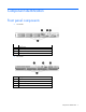
Component identification Front panel components • SFF model Item Description 1 Optical drive 2 Serial label pull tab 3 USB connectors (2) 4 Drive bays • LFF model Item Description 1 Optical drive 2 Serial label pull tab 3 USB connectors (2) 4 Drive bays Component identification 7
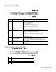
Front panel LEDs Item Description Status 1 Internal health LED Green = Normal Amber = System degraded Red = System critical Off = Normal (when in standby mode) 2 NIC 1 link/activity LED Green = Network link Flashing green = Network link and activity Off = No network link If the power is off, view the LEDs on the RJ-45 connector.
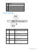
Item Description 5 10/100/1000 NIC 1 connector/ shared iLO management port 6 HP dedicated iLO management port (optional) 7 USB connectors (4) 8 T10/T15 tool 9 Slot 1 PCIe2 x16 (16, 8, 4, 1) 10 Slot 2 PCIe2 x8 (4, 1) Rear panel LEDs Item Description Status 1 UID button/LED Blue = Identification Flashing blue = System is being managed remotely Off = Off 2 NIC2 link LED Green = 10M/100M/1G link speed Off = No connection 3 NIC2 activity LED Green = Linked to the network Flashing green
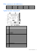
PCIe expansion slot definitions Slot Type Length Connector Interconnect 1 PCIe2 Full x16 x16 2 PCIe2 Half x8 x4 System board components Item Description 1 DIMM slots 1-4 2 Processor socket 3 System power connector (24 pin) 4 Fan connector 7 (Reserved) 5 Fan connector 8 (Reserved) 6 Fan connector 3 7 Fan connector 4 8 RPS connector 9 Fan connector 5 10 System battery 11 I2C cable connector 12 SATA connectors 13 SD card slot 14 Mini-SAS connector 15 Front panel c
Item Description 21 TPM connector 22 Power supply connector (4 pin) 23 System maintenance switch 24 HP dedicated iLO management connector System board LEDs Item LED description Status 1 Power supply 1 failure Red = Power supply 1 failed Off = Normal 2 Power supply 2 (redundant) failure Red = Power supply 2 failed Off = Normal System maintenance switch Position Default Function 1 Off Off = iLO 3 security is enabled On = iLO 3 security is disabled 2 Off Off = System configuration c
Position Default Function 8 Off Reserved 9 Off Reserved 10 Off Reserved When the system maintenance switch position 6 is set to the On position, the system is prepared to erase all system configuration settings from both CMOS and NVRAM. CAUTION: Clearing CMOS and/or NVRAM deletes configuration information. Be sure to properly configure the server or data loss could occur.
• 2 DIMMs: 2A+4B • 3 DIMMs: 2A+4B+1C • 4 DIMMs: All DIMMs SAS and SATA device numbering • LFF device bay numbering • SFF device bay numbering SAS and SATA drive LEDs Item Description 1 Fault/UID LED (amber/blue) 2 Online LED (green) Component identification 13
BBWC module LEDs Item ID Color Description 1 Green System Power LED. This LED illuminates steadily when the system is powered up and 12-V system power is available. This power supply is used to maintain the battery charge and provide supplementary power to the cache microcontroller. 2 Green Auxiliary Power LED. This LED illuminates steadily when 3.3 V auxiliary voltage is detected.
LED3 pattern LED4 pattern Interpretation — One flash per second The battery pack is below the minimum charge level and is being charged. Features that require a battery (such as write cache, capacity expansion, stripe size migration, and RAID migration) are temporarily unavailable until charging is complete. The recharge process takes between 15 minutes and 2 hours, depending on the initial capacity of the battery.
T-10/T15 Torx screwdriver The server includes a T-10/T-15 Torx screwdriver located on the rear panel of the server. Use the screwdriver to loosen screws during hardware configuration procedures.
Operations Power up the server 1. Connect each power cord to the server. 2. Connect each power cord to the power source. 3. Press the Power On/Standby button. The server exits standby mode and applies full power to the system. The system power LED changes from amber to green. Power down the server Before powering down the server for any upgrade or maintenance procedures, perform a backup of critical server data and programs.
To remove the server from an HP, Compaq branded, TELCO, or third-party rack: 1. Power down the server (on page 17). 2. Disconnect all peripheral cables and power cords from the server rear panel. 3. Loosen the thumbscrews that secure the server faceplate to the front of the rack. 4. Remove the server from the rack. For more information, see the documentation that ships with the rack mounting option. 5. Place the server on a sturdy, level surface.
c. Remove the riser cage. Install the PCIe riser cage CAUTION: To prevent damage to the server or expansion boards, power down the server and remove all AC power cords before removing or installing the PCIe riser board assembly. 1. Install the PCIe riser cage. 2. Connect any internal cables for expansion boards. 3. Install the access panel (on page 18). 4. Install the server into the rack ("Installing the server into the rack" on page 25).
CAUTION: For proper cooling, do not operate the server without the access panel, baffles, expansion slot covers, or blanks installed. If the server supports hot-plug components, minimize the amount of time the access panel is open. 1. Power down the server (on page 17). 2. Remove the access panel (on page 18). 3. Remove the air baffle. Install the air baffle CAUTION: For proper cooling, do not operate the server without the access panel, baffles, expansion slot covers, or blanks installed.
2. Install the access panel (on page 18). 3. Power up the server ("Powering up and configuring the server" on page 26, on page 17).
Setup Optional installation services Delivered by experienced, certified engineers, HP Care Pack services help you keep your servers up and running with support packages tailored specifically for HP ProLiant systems. HP Care Packs let you integrate both hardware and software support into a single package. A number of service level options are available to meet your needs.
Space and airflow requirements Rack server To allow for servicing and adequate airflow, observe the following space and airflow requirements when deciding where to install a rack: • Leave a minimum clearance of 63.5 cm (25 in) in front of the rack. • Leave a minimum clearance of 76.2 cm (30 in) behind the rack. • Leave a minimum clearance of 121.9 cm (48 in) from the back of the rack to the back of another rack or row of racks.
CAUTION: To reduce the risk of damage to the equipment when installing third-party options: • Do not permit optional equipment to impede airflow around the server or to increase the internal rack temperature beyond the maximum allowable limits. • Do not exceed the manufacturer’s TMRA. Power requirements Installation of this equipment must comply with local and regional electrical regulations governing the installation of information technology equipment by licensed electricians.
WARNING: To reduce the risk of personal injury or damage to the equipment, be sure that: • • • • • The leveling jacks are extended to the floor. The full weight of the rack rests on the leveling jacks. The stabilizing feet are attached to the rack if it is a single-rack installation. The racks are coupled together in multiple-rack installations. Only one component is extended at a time. A rack may become unstable if more than one component is extended for any reason.
WARNING: To reduce the risk of electric shock, fire, or damage to the equipment, do not plug telephone or telecommunications connectors into RJ-45 connectors. 3. Connect the power cord to the rear of the server. 4. Install power cord anchors. 5. Connect the power cord to the AC power source. WARNING: To reduce the risk of electric shock or damage to the equipment: • Do not disable the power cord grounding plug. The grounding plug is an important safety feature.
Registering the server To register the server, see the HP Registration website (http://register.hp.com).
Hardware options installation Introduction If more than one option is being installed, read the installation instructions for all the hardware options and identify similar steps to streamline the installation process. WARNING: To reduce the risk of personal injury from hot surfaces, allow the drives and the internal system components to cool before touching them. CAUTION: To prevent damage to electrical components, properly ground the server before beginning any installation procedure.
The server memory control subsystem selects the proper rank within the DIMM when writing to or reading from the DIMM. Dual-rank DIMMs provide the greatest capacity with the existing memory technology. For example, if current DRAM technology supports 2-GB single-rank DIMMs, a dual-rank DIMM would be 4 GB. DIMM identification To determine DIMM characteristics, use the label attached to the DIMM and the following illustration and table.
Memory configuration To optimize server availability, the server supports ECC memory. ECC memory provides the greatest memory capacity for a given DIMM size, while providing single-bit memory error corrections, depending on the specific DIMM type. This mode is the default option for this server. For the latest memory configuration information, see the QuickSpecs on the HP website (http://www.hp.com). ECC memory configuration ECC memory is the default memory protection mode for this server.
5. Install the DIMM. 6. Install the air baffle (on page 20). 7. Install the access panel (on page 18). If you are installing DIMMs in Lockstep configuration, configure the mode in RBSU ("HP ROM-Based Setup Utility" on page 54). Drive options The server provides non-hot-plug capability through an embedded SATA controller. To obtain hot-plug capability, install an optional controller and hot-plug cable option kit.
Remove the component as indicated. Removing a drive IMPORTANT: Hot-plug capability and drive LED support are only available when a supported optional controller is installed in the server. To remove the component: 1. Back up all server data on the drive. 2. Power down the server (on page 17). CAUTION: To prevent improper cooling and thermal damage, do not operate the server unless all bays are populated with either a component or a blank. 3. Remove the drive.
Installing a hot-plug drive IMPORTANT: Hot-plug capability and drive LED support are only available when a supported optional controller is installed in the server. 1. Power down the server (on page 17). 2. Remove the existing drive blank ("Removing a drive blank" on page 31). 3. Prepare the drive. 4. Install the drive. Optical drive option To install the component: 1. Power down the server (on page 17). 2. Remove the server from the rack (on page 17).
3. Remove the access panel (on page 18). 4. Remove the air baffle (on page 19). 5. Remove the 9.5-mm optical drive blank. Retain the blank for future use. 6. Install the 9.5-mm optical drive assembly. When fully inserted, the assembly locking latch clicks. 7. Using a T-15 Torx screwdriver, secure the drive to the chassis.
8. Connect the optical drive and power cable to the optical drive. 9. Connect the power connector to the power supply backplane. 10. Connect the SATA cable to the system board. See the cabling section for correct cable routing ("Optical drive cabling" on page 51). 11. Install the air baffle (on page 20). 12. Install the access panel (on page 18). 13. Install the server into the rack ("Installing the server into the rack" on page 25). 14.
5. Press the knockout. 6. To remove the knockout from the chassis, twist and pull it. 7. Using a T-15 Torx screwdriver, install the dedicated iLO management port module. 8. Install the air baffle (on page 20). 9. Install the access panel (on page 18). 10. Install the server into the rack ("Installing the server into the rack" on page 25). 11. Power up the server ("Powering up and configuring the server" on page 26, on page 17). Expansion board option To install the component: 1.
3. Remove the access panel (on page 18). 4. Disconnect all internal cables connected to any existing expansion boards. 5. Remove the PCIe riser cage (on page 18). 6. Remove the expansion slot covers. 7. Install the expansion board. IMPORTANT: The server does not power up if the PCIe riser board assembly is not seated properly. 8. Install the PCIe riser cage (on page 19). 9. Connect all internal cables for expansion boards. 10. Install the access panel (on page 18). 11.
6. Install the storage controller. 7. Connect the storage controller cable to the controller and to the drive backplane. See the server installation sheet and the documentation that ships with the storage controller. IMPORTANT: The server does not power up if the PCI riser board assembly is not seated properly. 8. Install the PCIe riser cage (on page 19). 9. Install the access panel (on page 18). 10. Install the server into the rack ("Installing the server into the rack" on page 25). 11.
6. Install the cache module on the controller. 7. Connect the battery pack cable to the cache module.
8. Install the battery pack. 9. Route the cable ("BBWC battery cabling" on page 50). 10. Install the PCIe riser cage (on page 19). 11. Install the access panel (on page 18). 12. Install the server into the rack ("Installing the server into the rack" on page 25). 13. Power up the server ("Powering up and configuring the server" on page 26, on page 17). Redundant hot-plug power supply option (with cage) To install the component: 1. Power down the server (on page 17). 2. Remove all power: a.
10. Remove the rear bracket. 11. Remove the ATX power supply.
12. Install the redundant power supply cage. 13. Install the system board. 14. Connect all cables previously disconnected from the system board. 15. Route and connect power cables to the system board and the front drive cage. 16. Install the PCIe riser cage (on page 19). 17. Install the air baffle (on page 20). 18. Install the foam air baffle from the option kit: IMPORTANT: Two foam air baffles are provided in the option kit.
o Foam air baffle for an eight-bay SFF drive cage 19. Install the access panel (on page 18). 20. Install the server into the rack ("Installing the server into the rack" on page 25). 21. Depending on the configuration, install either two power supplies, or one power supply blank and one power supply.
o Power supply 22. Connect the power cord to the power supply. 23. Connect the power cord to the power source. 24. Power up the server ("Powering up and configuring the server" on page 26, on page 17). HP Trusted Platform Module option Use these instructions to install and enable a TPM on a supported server. This procedure includes three sections: 1. Installing the Trusted Platform Module board (on page 45). 2. Retaining the recovery key/password (on page 46). 3.
• When using BitLocker, always retain the recovery key/password. The recovery key/password is required to enter Recovery Mode after BitLocker detects a possible compromise of system integrity. • HP is not liable for blocked data access caused by improper TPM use. For operating instructions, see the encryption technology feature documentation provided by the operating system.
6. Install the TPM security rivet by pressing the rivet firmly into the system board. 7. Install the access panel (on page 18). 8. Install the server into the rack ("Installing the server into the rack" on page 25). 9. Power up the server ("Powering up and configuring the server" on page 26, on page 17). Retaining the recovery key/password The recovery key/password is generated during BitLocker™ setup, and can be saved and printed after BitLocker™ is enabled.
CAUTION: When a TPM is installed and enabled on the server, data access is locked if you fail to follow the proper procedures for updating the system or option firmware, replacing the system board, replacing a hard drive, or modifying OS application TPM settings. For more information on firmware updates and hardware procedures, see the HP Trusted Platform Module Best Practices White Paper on the HP website (http://www.hp.com/support).
Cabling Cabling overview This section provides guidelines that help you make informed decisions about cabling the server and hardware options to optimize performance. Server cabling CAUTION: When routing cables, always be sure that the cables are not in a position where they can be pinched or air flow can be blocked. IMPORTANT: Route the cables without blocking the airflow or other installed components. Use the cable clips installed in the chassis to manage cable routing.
Redundant power supply cabling Internal USB cabling Cabling 49
BBWC battery cabling • The Smart Array controller full height full length slot • The Smart Array controller low profile slot Cabling 50
Optical drive cabling SATA cabling • LFF model Cabling 51
• SFF model SAS cabling • LFF model Cabling 52
• SFF model Cabling 53
Configuration and utilities Configuration tools SmartStart software SmartStart is a collection of software that optimizes single-server setup, providing a simple and consistent way to deploy server configuration. SmartStart has been tested on many ProLiant server products, resulting in proven, reliable configurations.
• Displaying system information • Selecting the primary boot controller • Configuring memory options • Language selection For more information on RBSU, see the HP ROM-Based Setup Utility User Guide on the Documentation CD or the HP website (http://www.hp.com/support/smartstart/documentation). Using RBSU To use RBSU, use the following keys: • To access RBSU, press the F9 key during power-up when prompted. • To navigate the menu system, use the arrow keys.
For more information on RBSU, see the HP ROM-Based Setup Utility User Guide on the Documentation CD or the HP website (http://www.hp.com/support/smartstart/documentation). Boot options Near the end of the boot process, the boot options screen is displayed. This screen is visible for several seconds before the system attempts to boot from a supported boot device. During this time, you can do the following: • Access RBSU by pressing the F9 key.
configure arrays, see the Configuring Arrays on HP Smart Array Controllers Reference Guide on the HP website (http://www.hp.com/support/CASAC_RG_en). Option ROM Configuration for Arrays Before installing an operating system, you can use the ORCA utility to create the first logical drive, assign RAID levels, and establish online spare configurations.
Management tools Automatic Server Recovery ASR is a feature that causes the system to restart when a catastrophic operating system error occurs, such as a blue screen, ABEND (does not apply to HP ProLiant DL980 Servers), or panic. A system fail-safe timer, the ASR timer, starts when the System Management driver, also known as the Health Driver, is loaded. When the operating system is functioning properly, the system periodically resets the timer.
For more information about iLO 3 features (which may require an iLO Advanced Pack or iLO Advanced for BladeSystem license), see the iLO 3 documentation on the Documentation CD or on the HP website (http://www.hp.com/go/ilo). Erase Utility CAUTION: Perform a backup before running the System Erase Utility.
HP Insight Diagnostics survey functionality HP Insight Diagnostics (on page 59) provides survey functionality that gathers critical hardware and software information on ProLiant servers. This functionality supports operating systems that may not be supported by the server. For operating systems supported by the server, see the HP website (http://www.hp.com/go/supportos).
• HP Insight Remote Support Advanced: This software provides comprehensive remote monitoring and proactive service support for nearly all HP servers, storage, network, and SAN environments, plus selected non-HP servers that have a support obligation with HP. It is integrated with HP Systems Insight Manager. A dedicated server is recommended to host both HP Systems Insight Manager and HP Insight Remote Support Advanced. Details for both versions are available on the HP website (http://www.hp.
For more information about version control tools, see the HP Systems Insight Manager Help Guide and the Version Control User Guide on the HP Systems Insight Manager website (http://www.hp.com/go/hpsim). ProLiant Support Packs PSPs represent operating system-specific bundles of ProLiant optimized drivers, utilities, and management agents. Refer to the PSP website (http://h18000.www1.hp.com/products/servers/management/psp.html).
• Downloads the latest components from Web • Enables direct update of BMC firmware (iLO and LO100i) For more information about HP SUM and to access the HP Smart Update Manager User Guide, see the HP website (http://www.hp.com/go/hpsum/documentation). Change control and proactive notification HP offers Change Control and Proactive Notification to notify customers 30 to 60 days in advance of upcoming hardware and software changes on HP commercial products.
Troubleshooting Pre-diagnostic steps WARNING: To avoid potential problems, ALWAYS read the warnings and cautionary information in the server documentation before removing, replacing, reseating, or modifying system components. IMPORTANT: This guide provides information for multiple servers. Some information may not apply to the server you are troubleshooting. Refer to the server documentation for information on procedures, hardware options, software tools, and operating systems supported by the server. 1.
This symbol indicates the presence of a hot surface or hot component. If this surface is contacted, the potential for injury exists. WARNING: To reduce the risk of injury from a hot component, allow the surface to cool before touching. 14.26 kg 31.4 lb This symbol indicates that the component exceeds the recommended weight for one individual to handle safely.
WARNING: To reduce the risk of personal injury or damage to the equipment: 14.26 kg 31.4 lb • Observe local occupation health and safety requirements and guidelines for manual handling. • Obtain adequate assistance to lift and stabilize the chassis during installation or removal. • The server is unstable when not fastened to the rails. • When mounting the server in a rack, remove the power supplies and any other removable module to reduce the overall weight of the product.
6. Collect all tools and utilities, such as a Torx screwdriver, loopback adapters, ESD wrist strap, and software utilities, necessary to troubleshoot the problem. o You must have the appropriate Health Drivers and Management Agents installed on the server. To verify the server configuration, connect to the System Management Homepage (http://h18013.www1.hp.com/products/servers/management/agents/index.html ) and select Version Control Agent.
• All optical drives (DVD-ROM, CD-ROM, and so forth) • All optional mezzanine cards • All expansion boards Before removing the components, be sure to determine the minimum configuration for each component and follow all guidelines in the server user guide. Always use the recommended minimum configuration above before removing any processors. If you are unable to isolate the issue with the configuration above, you will then remove all but one of the processors.
For the location of server LEDs and information on their statuses, see the server documentation on the HP website (http://www.hp.com/support). Troubleshooting flowcharts To effectively troubleshoot a problem, HP recommends that you start with the first flowchart in this section, "Start diagnosis flowchart (on page 69)," and follow the appropriate diagnostic path. If the other flowcharts do not provide a troubleshooting solution, follow the diagnostic steps in "General diagnosis flowchart (on page 70).
General diagnosis flowchart The General diagnosis flowchart provides a generic approach to troubleshooting. If you are unsure of the problem, or if the other flowcharts do not fix the problem, use the following flowchart. Item See 1 "Symptom information (on page 66)" 2 "Loose connections (on page 68)" 3 "Service notifications (on page 68)" 4 The most recent version of a particular server or option firmware is available on the HP Support website (http://www.hp.com/support).
Item See 5 "General memory problems are occurring" in the HP ProLiant Servers Troubleshooting Guide located on the Documentation CD or see "Troubleshooting resources" 6 Server maintenance and service guide, located on the Documentation CD or the HP website (http://www.hp.
Server power-on problems flowchart Symptoms: • The server does not power on. • The system power LED is off or amber.
• The external health LED is red or amber. • The internal health LED is red or amber. NOTE: For the location of server LEDs and information on their statuses, refer to the server documentation.
Troubleshooting 74
POST problems flowchart Symptoms: • Server does not complete POST NOTE: The server has completed POST when the system attempts to access the boot device.
Item See 13 • • "Server information you need" in the HP ProLiant Servers Troubleshooting Guide located on the Documentation CD or see "Troubleshooting resources" "Operating system information you need" in the HP ProLiant Servers Troubleshooting Guide located on the Documentation CD or see "Troubleshooting resources" Troubleshooting 76
OS boot problems flowchart Symptoms: • Server does not boot a previously installed operating system • Server does not boot SmartStart Possible causes: • Corrupted operating system • Hard drive subsystem problem • Incorrect boot order setting in RBSU Item See 1 HP ROM-Based Setup Utility User Guide (http://www.hp.
Server fault indications flowchart Symptoms: • Server boots, but a fault event is reported by Insight Management Agents • Server boots, but the internal health LED, external health LED, or component health LED is red or amber NOTE: For the location of server LEDs and information on their statuses, refer to the server documentation.
Possible causes: • Improperly seated or faulty internal or external component • Unsupported component installed • Redundancy failure • System overtemperature condition Item See 1 • • "Integrated Management Log (on page 60)" or in the HP ProLiant Servers Troubleshooting Guide located on the Documentation CD or see "Troubleshooting resources" "Event list error messages" in the HP ProLiant Servers Troubleshooting Guide located on the Documentation CD or see "Troubleshooting resources" 2 "Compone
POST error messages and beep codes For a complete listing of error messages, refer to the "POST error messages" in the HP ProLiant Servers Troubleshooting Guide located on the Documentation CD or on the HP website (http://www.hp.com/support).
WARNING: To avoid potential problems, ALWAYS read the warnings and cautionary information in the server documentation before removing, replacing, reseating, or modifying system components.
Battery If the server no longer automatically displays the correct date and time, you may need to replace the battery that provides power to the real-time clock. Under normal use, battery life is 5 to 10 years. WARNING: The computer contains an internal lithium manganese dioxide, a vanadium pentoxide, or an alkaline battery pack. A risk of fire and burns exists if the battery pack is not properly handled. To reduce the risk of personal injury: • • • • Do not attempt to recharge the battery.
Regulatory compliance notices Regulatory compliance identification numbers For the purpose of regulatory compliance certifications and identification, this product has been assigned a unique regulatory model number. The regulatory model number can be found on the product nameplate label, along with all required approval markings and information. When requesting compliance information for this product, always refer to this regulatory model number.
Declaration of conformity for products marked with the FCC logo, United States only This device complies with Part 15 of the FCC Rules. Operation is subject to the following two conditions: (1) this device may not cause harmful interference, and (2) this device must accept any interference received, including interference that may cause undesired operation. For questions regarding this product, contact us by mail or telephone: • Hewlett-Packard Company P. O.
• Ecodesign Directive 2009/125/EC, where applicable CE compliance of this product is valid if powered with the correct CE-marked AC adapter provided by HP. Compliance with these directives implies conformity to applicable harmonized European standards (European Norms) that are listed in the EU Declaration of Conformity issued by HP for this product or product family and available (in English only) either within the product documentation or at the following HP website (http://www.hp.
BSMI notice Korean class A notice Chinese notice Class A equipment Laser compliance This product may be provided with an optical storage device (that is, CD or DVD drive) and/or fiber optic transceiver. Each of these devices contains a laser that is classified as a Class 1 Laser Product in accordance with US FDA regulations and the IEC 60825-1. The product does not emit hazardous laser radiation. Each laser product complies with 21 CFR 1040.10 and 1040.
Battery replacement notice WARNING: The computer contains an internal lithium manganese dioxide, a vanadium pentoxide, or an alkaline battery pack. A risk of fire and burns exists if the battery pack is not properly handled. To reduce the risk of personal injury: • Do not attempt to recharge the battery. • Do not expose the battery to temperatures higher than 60°C (140°F). • Do not disassemble, crush, puncture, short external contacts, or dispose of in fire or water.
Electrostatic discharge Preventing electrostatic discharge To prevent damaging the system, be aware of the precautions you need to follow when setting up the system or handling parts. A discharge of static electricity from a finger or other conductor may damage system boards or other static-sensitive devices. This type of damage may reduce the life expectancy of the device. To prevent electrostatic damage: • Avoid hand contact by transporting and storing products in static-safe containers.
Specifications Environmental specifications Specification Value Temperature range* Operating 10°C to 35°C (50°F to 95°F) Non-operating -30°C to 60°C (-22°F to 140°F) Relative humidity (non-condensing) Operating, maximum wet bulb 10% to 90% temperature of 28°C (82.4°F) Non-operating, maximum wet 5% to 95% bulb temperature of 38.7°C (101.7°F) * All temperature ratings shown are for sea level. An altitude derating of 1°C per 304.8 m (1.8°F per 1,000 ft) to 3048 m (10,000 ft) is applicable.
Efficiency Not less than 70% at 100%load Not less than 70% at 50%load Not less than 70% at 20%load Rated output power 400 W • HP ProLiant Common slot 400 W power supply Specification Value Input requirements Rated input voltage 100 to 127 VAC, 200 to 240 VAC Rated input frequency 47 Hz to 63 Hz Rated input current 6 A at 100 VAC 3 A at 200 VAC Rated input power 570 W at 230 VAC Power supply output Efficiency Not less than 85% at 100% load Not less than 89% at 50% load Not less than 85% at 2
Support and other resources Before you contact HP Be sure to have the following information available before you call HP: • Active Health System log Download and have available an Active Health System log for 3 days before the failure was detected. For more information, see the HP iLO 4 User Guide or HP Intelligent Provisioning User Guide on the HP website (http://www.hp.com/go/ilo/docs).
providers or service partners) identifies that the repair can be accomplished by the use of a CSR part, HP will ship that part directly to you for replacement. There are two categories of CSR parts: • Mandatory—Parts for which customer self repair is mandatory. If you request HP to replace these parts, you will be charged for the travel and labor costs of this service. • Optional—Parts for which customer self repair is optional. These parts are also designed for customer self repair.
Pour plus d'informations sur le programme CSR de HP, contactez votre Mainteneur Agrée local. Pour plus d'informations sur ce programme en Amérique du Nord, consultez le site Web HP (http://www.hp.com/go/selfrepair). Riparazione da parte del cliente Per abbreviare i tempi di riparazione e garantire una maggiore flessibilità nella sostituzione di parti difettose, i prodotti HP sono realizzati con numerosi componenti che possono essere riparati direttamente dal cliente (CSR, Customer Self Repair).
HINWEIS: Einige Teile sind nicht für Customer Self Repair ausgelegt. Um den Garantieanspruch des Kunden zu erfüllen, muss das Teil von einem HP Servicepartner ersetzt werden. Im illustrierten Teilekatalog sind diese Teile mit „No“ bzw. „Nein“ gekennzeichnet. CSR-Teile werden abhängig von der Verfügbarkeit und vom Lieferziel am folgenden Geschäftstag geliefert. Für bestimmte Standorte ist eine Lieferung am selben Tag oder innerhalb von vier Stunden gegen einen Aufpreis verfügbar.
sustituciones que lleve a cabo el cliente, HP se hará cargo de todos los gastos de envío y devolución de componentes y escogerá la empresa de transporte que se utilice para dicho servicio. Para obtener más información acerca del programa de Reparaciones del propio cliente de HP, póngase en contacto con su proveedor de servicios local. Si está interesado en el programa para Norteamérica, visite la página web de HP siguiente (http://www.hp.com/go/selfrepair).
Opcional – Peças cujo reparo feito pelo cliente é opcional. Essas peças também são projetadas para o reparo feito pelo cliente. No entanto, se desejar que a HP as substitua, pode haver ou não a cobrança de taxa adicional, dependendo do tipo de serviço de garantia destinado ao produto. OBSERVAÇÃO: Algumas peças da HP não são projetadas para o reparo feito pelo cliente. A fim de cumprir a garantia do cliente, a HP exige que um técnico autorizado substitua a peça.
Support and other resources 97
Support and other resources 98
Acronyms and abbreviations ABEND abnormal end ACU Array Configuration Utility ASR Automatic Server Recovery BBWC battery-backed write cache CSA Canadian Standards Association CSR Customer Self Repair DDR double data rate IEC International Electrotechnical Commission iLO Integrated Lights-Out IML Integrated Management Log NMI nonmaskable interrupt NVRAM nonvolatile memory Acronyms and abbreviations 99
ORCA Option ROM Configuration for Arrays PCIe Peripheral Component Interconnect Express POST Power-On Self Test PSP HP ProLiant Support Pack RBSU ROM-Based Setup Utility RDIMM registered dual in-line memory module RDP Rapid Deployment Pack SAS serial attached SCSI SATA serial ATA SFF small form factor SIM Systems Insight Manager TMRA recommended ambient operating temperature TPM Trusted Platform Module UDIMM unregistered dual in-line memory module Acronyms and abbreviations 100
UID unit identification USB universal serial bus VCA Version Control Agent Acronyms and abbreviations 101
Documentation feedback HP is committed to providing documentation that meets your needs. To help us improve the documentation, send any errors, suggestions, or comments to Documentation Feedback (mailto:docsfeedback@hp.com). Include the document title and part number, version number, or the URL when submitting your feedback.
Index A D access panel 18 air baffle 19, 20 Array Configuration Utility (ACU) 55 ASR (Automatic Server Recovery) 57 authorized reseller 89 auto-configuration process 54 Automatic Server Recovery (ASR) 57 diagnostic tools 53, 57, 58 diagnostics utility 58 DIMM identification 28 DIMM population guidelines 29 DIMM slot locations 12 DIMMs 12, 27 DIMMs, single- and dual-rank 27 drive blank 30 drive information 30 drivers 60 drives 30 drives, removing 31 B battery 80, 85 battery-backed write cache battery pac
H hardware options installation 25, 27 health driver 57 health LEDs 67 help resources 89 hot-plug drive, installing 32 HP Insight Diagnostics 58, 59 HP Insight Remote Support software 59 HP Smart Update Manager overview 61 HP technical support 89 I identification number 81 iLO (Integrated Lights-Out) 57 iLO 3 (Integrated Lights-Out 3) 57 iLO ports 34 IML (Integrated Management Log) 59 Important Safety Information document 63 Insight Diagnostics 58, 59, 60 installation services 22 installation, server optio
rear panel LEDs 9 redundant power supply 39 registering the server 26 regulatory compliance notices 81 removing PCIe riser cage 18 removing server from rack 17 removing the access panel 18 required information 89 retaining the recovery key/password 45 ROMPaq utility 57 RPS cabling 48 S safety considerations 24, 63, 86 SAS and SATA device numbers 13 SAS drive LEDs 13 SAS hard drive cabling 51 SATA drive LEDs 13 scripted installation 53 serial number 56 series number 81 server cabling 47 server fault indicat