HP ProLiant BL660c Gen8 Server Blade User Guide Abstract This document is for the person who installs, administers, and troubleshoots servers and storage systems. HP assumes you are qualified in the servicing of computer equipment and trained in recognizing hazards in products with hazardous energy levels.
© Copyright 2014 Hewlett-Packard Development Company, L.P. The information contained herein is subject to change without notice. The only warranties for HP products and services are set forth in the express warranty statements accompanying such products and services. Nothing herein should be construed as constituting an additional warranty. HP shall not be liable for technical or editorial errors or omissions contained herein. Microsoft® and Windows® are U.S. registered trademarks of Microsoft Corporation.
Contents Component identification ............................................................................................................... 6 Front panel components ................................................................................................................................ 6 Front panel LEDs and buttons ......................................................................................................................... 6 Hot-plug drive LED definitions ..........................
Mezzanine card option .............................................................................................................................. 41 HP Trusted Platform Module option .............................................................................................................. 43 Installing the Trusted Platform Module board ....................................................................................... 44 Retaining the recovery key/password.........................................
Electrostatic discharge ................................................................................................................. 66 Preventing electrostatic discharge ................................................................................................................ 66 Grounding methods to prevent electrostatic discharge .................................................................................... 66 Specifications ...............................................................
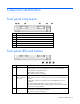
Component identification Front panel components Item Description 1 HP c-Class Blade SUV cable connector (behind the serial label pull tab) 2 Serial label pull tab 3 Drive bay 1 4 Drive bay 2 5 Server blade release lever 6 Server blade release button Front panel LEDs and buttons Item Description Status 1 Health status LED bar Solid Green = Normal (System is powered on.) Flashing Green = Power On/Standby Button service is being initialized.
Item Description 4 FlexibleLOM LED Status Green = Network linked Flashing Green = Network activity Off = No link or activity Hot-plug drive LED definitions Item LED Status Definition 1 Locate Solid blue The drive is being identified by a host application. Flashing blue The drive carrier firmware is being updated or requires an update. Rotating green Drive activity Off No drive activity Solid white Do not remove the drive.
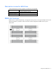
System board components Item Description 1 HP c-Class Blade SUV cable connector 2 Processor 3 DIMM slots (8) 3 Processor socket 3 (populated) 4 Processor 1 DIMM slots (8) 5 Processor socket 1 (populated) 6 System board thumbscrew 7 System maintenance switch 8 TPM connector 9 Mezzanine assembly guide pins 10 Enclosure connector 11 Mezzanine connector 1 (Type A mezzanine only) 12 Mezzanine connector 2 (Type A or Type B mezzanine) 13 FlexibleLOM 2 connectors (2) 14 Internal USB co
Mezzanine connector definitions A PCIe x8 mezzanine connector supports x16 cards at up to x8 speeds. Item PCIe Mezzanine connector 1 x8, Type A mezzanine card only Mezzanine connector 2 x16, Type A or B mezzanine card Mezzanine connector 3 x16, Type A or B mezzanine card DIMM slot locations DIMM slots are numbered sequentially (1 through 8) for each processor. The supported AMP modes use the alpha assignments for population order and the slot numbers designate the DIMM slot ID for spare replacement.
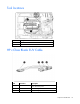
Tool locations Item Description 1 DIMM tool 2 T-15 Torx screwdriver HP c-Class Blade SUV Cable Item Connector Description 1 Server blade For connecting to the SUV connector on the server blade front panel 2 Video For connecting a video monitor 3 USB For connecting up to two USB devices Component identification 10
Item Connector Description 4 Serial For trained personnel to connect a null modem serial cable and perform advanced diagnostic procedures Component identification 11
Operations Power up the server blade The Onboard Administrator initiates an automatic power-up sequence when the server blade is installed. If the default setting is changed, use one of the following methods to power up the server blade: • Use a virtual power button selection through iLO. • Press and release the Power On/Standby button. When the server blade goes from the standby mode to the full power mode, the system power LED changes from amber to solid green.
o poweroff server [bay number] force This form of the command forces the server blade to enter standby mode without properly exiting applications and the OS. If an application stops responding, this method forces a shutdown. • Use the Onboard Administrator GUI to initiate a shutdown: a. Select the Enclosure Information tab. b. In the Device Bays item, select the Overall checkbox. c.
Remove the access panel To remove the component: 1. Power down the server blade (on page 12). 2. Remove the server blade (on page 13). 3. Press the access panel release button. 4. Slide the access panel towards the rear of the server blade, and then lift to remove the panel. Remove a drive 1. Back up all server blade data on the drive. 2. Remove the drive.
5. Remove the center DIMM baffle. Remove the left DIMM baffle To remove the component: 1. Power down the server blade (on page 12). 2. Remove the server blade (on page 13). 3. Remove the access panel (on page 14). 4. Disconnect any cables that may be routed across the DIMM baffle. 5. Remove the left DIMM baffle.
Remove the right DIMM baffle To remove the component: 1. Power down the server blade (on page 12). 2. Remove the server blade (on page 13). 3. Remove the access panel (on page 14). 4. Disconnect any cables that may be routed across the DIMM baffle. 5. Remove the right DIMM baffle. Remove the front panel/drive cage assembly To remove the component: 1. Power down the server blade (on page 12). 2. Remove the server blade (on page 13). 3. Remove the access panel (on page 14). 4.
8. Extend the serial label pull tab. 9. Remove the front panel/drive cage assembly. Remove the FBWC capacitor pack To remove the component: 1. Power down the server blade (on page 12). 2. Remove the server blade (on page 13). 3. Remove the access panel (on page 14). 4. Locate the capacitor pack on the drive cage. For more information, see "FBWC capacitor pack cabling (on page 47).
5. Remove the capacitor pack from the carrier.
Setup Installing an HP BladeSystem c-Class enclosure Before performing any server blade-specific procedures, install an HP BladeSystem c-Class enclosure. The most current documentation for server blades and other HP BladeSystem components is available at the HP website (http://www.hp.com/go/bladesystem/documentation). Documentation is also available in the following locations: • Documentation CD that ships with the enclosure • HP website (http://www.hp.
Removing a c7000 device bay divider 1. Slide the device bay shelf locking tab to the left to open it. 2. Push the device bay shelf back until it stops, lift the right side slightly to disengage the two tabs from the divider wall, and then rotate the right edge downward (clockwise).
3. Lift the left side of the device bay shelf to disengage the three tabs from the divider wall, and then remove it from the enclosure. Removing a c3000 device bay mini-divider or device bay divider 1. Slide the locking tab down. 2.
Push the divider toward the back of the enclosure until the divider drops out of the chassis. o c3000 divider: a. Push the divider toward the back of the enclosure until it stops. b. Slide the divider to the left to disengage the tabs from the wall. c. Rotate the divider clockwise. d. Remove the divider from the enclosure. Installing interconnect modules For specific steps to install interconnect modules, see the documentation that ships with the interconnect module.
Interconnect bay numbering and device mapping • HP BladeSystem c7000 Enclosure • HP BladeSystem c3000 Enclosure To support network connections for specific signals, install an interconnect module in the bay corresponding to the embedded adapter or mezzanine signals.
Server blade signal Mezzanine 3 c7000 interconnect bay c3000 interconnect bay 5 and 6** 3 and 4 7 and 8* 3 and 4 Interconnect bay labels * Dual port mezzanine card ports and four-port mezzanine card ports 1 and 2 ** Four-port mezzanine card ports 3 and 4 For detailed port mapping information, see the HP BladeSystem enclosure installation poster or the HP BladeSystem enclosure setup and installation guide on the HP website (http://www.hp.com/go/bladesystem/documentation).
2. Install the server blade. Assembling a full height blank CAUTION: To prevent improper cooling and thermal damage, do not operate the server blade or the enclosure unless all drive and device bays are populated with either a component or a blank. 1. Obtain the coupler plate: o If you are using a device bay blank that came with the enclosure, the coupler plate can be found with the contents of the full-height device shipping box.
2. Fit the coupler plate into the slots on top of the blank, and then slide the coupler plate back until it snaps into place. 3. Fit the slots on the bottom of the second blank on to the tabs on the coupler plate, and then slide the second blank forward until it snaps in place. 4. Install the full-height blank into the device bay. Completing the configuration To complete the server blade and HP BladeSystem configuration, see the overview card that ships with the enclosure.
Hardware options installation Introduction If more than one option is being installed, read the installation instructions for all the hardware options and identify similar steps to streamline the installation process. WARNING: To reduce the risk of personal injury from hot surfaces, allow the drives and the internal system components to cool before touching them. CAUTION: To prevent damage to electrical components, properly ground the server before beginning any installation procedure.
3. Install the drive. 4. Determine the status of the drive from the drive LED definitions ("Hot-plug drive LED definitions" on page 7). Processor option WARNING: To reduce the risk of personal injury from hot surfaces, allow the drives and the internal system components to cool before touching them. CAUTION: To prevent possible server blade malfunction and damage to the equipment, multiprocessor configurations must contain processors with the same part number.
9. Remove the heatsink blank. Retain the heatsink blank for future use. 10. Open each of the processor locking levers in the order indicated, and then open the processor retaining bracket.
11. Remove the clear processor socket cover. Retain the processor socket cover for future use. 12. Install the processor. Verify that the processor is fully seated in the processor retaining bracket by visually inspecting the processor installation guides on either side of the processor. THE PINS ON THE SYSTEM BOARD ARE VERY FRAGILE AND EASILY DAMAGED. CAUTION: THE PINS ON THE SYSTEM BOARD ARE VERY FRAGILE AND EASILY DAMAGED.
CAUTION: Do not press down on the processor. Pressing down on the processor may cause damage to the processor socket and the system board. Press only in the area indicated on the processor retaining bracket. 14. Press and hold the processor retaining bracket in place, and then close each processor locking lever. Press only in the area indicated on the processor retaining bracket. 15. Remove the thermal interface protective cover from the heatsink.
CAUTION: Heatsink retaining screws should be tightened in diagonally opposite pairs (in an "X" pattern). 16. Install the heatsink. 17. Install all DIMM baffles. 18. Install the front panel/drive cage assembly. 19. Install all FBWC capacitor packs ("FBWC capacitor pack options" on page 39). 20. Install all drives ("Drive option" on page 27). 21. Install the access panel. Memory options IMPORTANT: This server blade does not support mixing LRDIMMs or RDIMMs.
The server model using Intel Ivy Bridge (v2) processors supports the following DIMM speeds: • Single- and dual-rank PC3-12800 (DDR-1600) RDIMMs operating at up to 1600 MT/s • Single- and dual-rank PC3-14900 (DDR-1866) RDIMMs operating at up to 1866 MT/s • Quad-rank PC3L-14900 (DDR3-1866) LRDIMMs operating at up to 1866 MT/s Speed, voltage, and capacity for server models with Sandy Bridge processors DIMM type DIMM rank DIMM capacity Native speed (MT/s) Voltage RDIMM Single-rank 4 GB 1333 LV
DIMM type DIMM rank 1 DIMM per channel 2 DIMMs per channel RDIMM (LV) Single-rank (4 GB) 1600 1600 RDIMM (STD) Single-rank (4 GB) 1866 1866 RDIMM (LV) Single-rank (8 GB) 1600 1600 RDIMM (STD) Single-rank (8 GB) 1866 1866 RDIMM (LV) Dual-rank (8 GB) 1600 1600 RDIMM (STD) Dual-rank (8 GB) 1866 1866 RDIMM (LV) Dual-rank (16 GB) 1600 1600 RDIMM (STD) Dual-rank (16 GB) 1866 1866 LRDIMM (STD) Quad-rank (32 GB) 1866 1866 HP SmartMemory HP SmartMemory, introduced for Gen8 ser
A single-rank DIMM has one set of memory chips that is accessed while writing to or reading from the memory. A dual-rank DIMM is similar to having two single-rank DIMMs on the same module, with only one rank accessible at a time. A quad-rank DIMM is, effectively, two dual-rank DIMMs on the same module. Only one rank is accessible at a time. The server blade memory control subsystem selects the proper rank within the DIMM when writing to or reading from the DIMM.
Item Description Definition E = UDIMM (unbuffered with ECC) L = LRDIMM (load reduced) For the latest supported memory information, see the QuickSpecs on the HP website (http://h18000.www1.hp.com/products/quickspecs/ProductBulletin.html). At the website, choose the geographic region, and then locate the product by name or product category.
Online Spare memory configuration Online spare memory provides protection against degraded DIMMs by reducing the likelihood of uncorrected memory errors. This protection is available without any operating system support. Online spare memory protection dedicates one rank of each memory channel for use as spare memory. The remaining ranks are available for OS and application use.
Advanced ECC population guidelines For Advanced ECC mode configurations, observe the following guidelines: • Observe the general DIMM slot population guidelines (on page 37). • DIMMs may be installed individually. Online spare population For Online Spare memory mode configurations, observe the following guidelines: • Observe the general DIMM slot population guidelines (on page 37). • Each channel must have a valid online spare configuration.
6. Use the DIMM tool to open the DIMM slot. 7. Install the DIMM. 8. Install all DIMM baffles. 9. Install the access panel. To configure the memory mode, use RBSU ("HP ROM-Based Setup Utility" on page 56). FBWC capacitor pack options To install the component: 1. Power down the server blade (on page 12). 2. Remove the server blade (on page 13). 3. Remove the access panel (on page 14). 4. Install the FBWC capacitor pack in one of the three capacitor pack carriers.
5. Route the FBWC capacitor pack cable. The DIMM baffles may be removed to route the cables, if necessary.
o 6. Routing and connecting the FBWC capacitor pack cable to the mezzanine 3 connector option Install the access panel. Mezzanine card option Optional mezzanine cards are classified as Type A mezzanine cards and Type B mezzanine cards. The type of the mezzanine card determines where it can be installed in the server blade. • Install Type A mezzanine cards on Mezzanine 1 connector, Mezzanine 2 connector, or Mezzanine 3 connector.
4. Remove the mezzanine assembly from the server blade. 5. Align the mezzanine card with the guide pins on the mezzanine assembly.
6. Install the mezzanine card in the mezzanine assembly, and then tighten the mezzanine card screws to secure the card to the mezzanine assembly. 7. Align the mezzanine assembly with the guide pins on the system board, and then install the mezzanine assembly on the system board. 8. Press down firmly on the mezzanine assembly handles, and then close the mezzanine assembly latch. 9. Install the access panel. 10. Install the server blade ("Installing a server blade" on page 24).
1. Installing the Trusted Platform Module board (on page 44). 2. Retaining the recovery key/password (on page 45). 3. Enabling the Trusted Platform Module (on page 46). Enabling the TPM requires accessing RBSU ("HP ROM-Based Setup Utility" on page 56). For more information about RBSU, see the HP website (http://www.hp.com/support/rbsu). TPM installation requires the use of drive encryption technology, such as the Microsoft Windows BitLocker Drive Encryption feature.
5. Install the TPM board. Press down on the connector to seat the board ("System board components" on page 8). 6. Install the TPM security rivet by pressing the rivet firmly into the system board. 7. Install the access panel. 8. Install the server blade ("Installing a server blade" on page 24). 9. Power up the server blade (on page 12). Retaining the recovery key/password The recovery key/password is generated during BitLocker™ setup, and can be saved and printed after BitLocker™ is enabled.
• Always store copies of the recovery key/password away from the server blade. • Do not save the recovery key/password on the encrypted hard drive. Enabling the Trusted Platform Module 1. When prompted during the start-up sequence, access RBSU by pressing the F9 key. 2. From the Main Menu, select Server Security. 3. From the Server Security Menu, select Trusted Platform Module. 4. From the Trusted Platform Module Menu, select TPM Functionality. 5.
Cabling Cabling resources Cabling configurations and requirements vary depending on the product and installed options. For more information about product features, specifications, options, configurations, and compatibility, see the product QuickSpecs on the HP Product Bulletin website (http://www.hp.com/go/productbulletin).
• FBWC capacitor pack cable to the cache module option • FBWC capacitor pack cabling to the mezzanine 3 connector option For capacitor pack and cabling instructions, see "FBWC capacitor pack options (on page 39)." Using the HP c-Class Blade SUV Cable The HP c-Class Blade SUV Cable enables the user to perform server blade administration, configuration, and diagnostic procedures by connecting video and USB devices directly to the server blade.
Connecting locally to a server blade with video and USB devices Use the SUV cable to connect a monitor and any of the following USB devices: • USB hub • USB keyboard • USB mouse • USB CD/DVD-ROM drive Numerous configurations are possible. This section offers two possible configurations. For more information, see "USB support (on page 60)." Accessing a server blade with local KVM For this configuration, a USB hub is not necessary. To connect additional devices, use a USB hub.
Accessing local media devices Use the following configuration when configuring a server blade or loading software updates and patches from a USB CD/DVD-ROM. Use a USB hub when connecting a USB CD-ROM drive to the server blade. The USB hub provides additional connections. 1. Open the serial label pull tab and connect the HP c-Class Blade SUV cable to the server blade. 2. Connect the video connector to a monitor. 3. Connect a USB hub to one USB connector. 4.
Software and configuration utilities Server mode The software and configuration utilities presented in this section operate in online mode, offline mode, or in both modes.
iLO enables and manages the Active Health System (on page 52) and also features Agentless Management. All key internal subsystems are monitored by iLO. SNMP alerts are sent directly by iLO regardless of the host operating system or even if no host operating system is installed. HP Insight Remote Support software (on page 55) is also available in HP iLO with no operating system software, drivers, or agents.
The data that is collected is managed according to the HP Data Privacy policy. For more information see the HP website (http://www.hp.com/go/privacy). The Active Health System log, in conjunction with the system monitoring provided by Agentless Management or SNMP Pass-thru, provides continuous monitoring of hardware and configuration changes, system status, and service alerts for various server components. The Agentless Management Service is available in the SPP, which is a disk image (.
see the Resources tab on the HP website (http://www.hp.com/go/ilo). For consolidated drive and firmware update packages, see the HP Systems and Server Software Management page on the HP website (http://www.hp.com/go/SmartUpdate).
HP Insight Remote Support software HP strongly recommends that you register your device for remote support to enable enhanced delivery of your HP Warranty, HP Care Pack Service, or HP contractual support agreement.
To download HP SUM, see the HP website (http://www.hp.com/go/hpsum/download). To access the HP Smart Update Manager User Guide, see the HP SUM Information Library (http://www.hp.com/go/hpsum/documentation).
NOTE: The server may not support all the following examples. Drives installed Drives used RAID level 1 1 RAID 0 2 2 RAID 1 3, 4, 5, or 6 3, 4, 5, or 6 RAID 5 More than 6 0 None To change any ORCA default settings and override the auto-configuration process, press the F8 key when prompted. For more information on RBSU, see the HP ROM-Based Setup Utility User Guide on the Documentation CD or the HP RBSU Information Library (http://www.hp.com/go/rbsu/docs).
Warning: The serial number should ONLY be modified by qualified service personnel. This value should always match the serial number located on the chassis. 5. Press the Enter key to clear the warning. 6. Enter the serial number and press the Enter key. 7. Select Product ID. The following warning appears: Warning: The Product ID should ONLY be modified by qualified service personnel. This value should always match the Product ID located on the chassis. 8. Enter the product ID and press the Enter key.
• If an optional controller is installed, when the system recognizes the controller during POST, press F5. For optimum performance, the minimum display settings are 1024 × 768 resolution and 16-bit color. Servers running Microsoft® operating systems require one of the following supported browsers: • Internet Explorer 6.0 or later • Mozilla Firefox 2.0 or later For Linux servers, see the README.TXT file for additional browser and support information.
Automatic Server Recovery ASR is a feature that causes the system to restart when a catastrophic operating system error occurs, such as a blue screen, ABEND (does not apply to HP ProLiant DL980 Servers), or panic. A system fail-safe timer, the ASR timer, starts when the System Management driver, also known as the Health Driver, is loaded. When the operating system is functioning properly, the system periodically resets the timer.
IMPORTANT: Always perform a backup before installing or updating device drivers. The server blade includes new hardware that may not have driver support on all OS installation media. If you are installing an Intelligent Provisioning-supported OS, use Intelligent Provisioning (on page 53) and its Configure and Install feature to install the OS and latest supported drivers. If you do not use Intelligent Provisioning to install an OS, drivers for some of the new hardware are required.
Change control and proactive notification HP offers Change Control and Proactive Notification to notify customers 30 to 60 days in advance of upcoming hardware and software changes on HP commercial products. For more information, refer to the HP website (http://www.hp.com/go/pcn).
Troubleshooting Troubleshooting resources The HP ProLiant Gen8 Troubleshooting Guide, Volume I: Troubleshooting provides procedures for resolving common problems and comprehensive courses of action for fault isolation and identification, issue resolution, and software maintenance on ProLiant servers and server blades. To view the guide, select a language: • English (http://www.hp.com/support/ProLiant_TSG_v1_en) • French (http://www.hp.com/support/ProLiant_TSG_v1_fr) • Spanish (http://www.hp.
Battery replacement If the server blade no longer automatically displays the correct date and time, then replace the battery that provides power to the real-time clock. Under normal use, battery life is 5 to 10 years. WARNING: The computer contains an internal lithium manganese dioxide, a vanadium pentoxide, or an alkaline battery pack. A risk of fire and burns exists if the battery pack is not properly handled. To reduce the risk of personal injury: • • • • Do not attempt to recharge the battery.
Regulatory compliance notices Safety and regulatory compliance For safety, environmental, and regulatory information, see Safety and Compliance Information for Server, Storage, Power, Networking, and Rack Products, available at the HP website (http://www.hp.com/support/Safety-Compliance-EnterpriseProducts). Turkey RoHS material content declaration Ukraine RoHS material content declaration Warranty information HP ProLiant and X86 Servers and Options (http://www.hp.
Electrostatic discharge Preventing electrostatic discharge To prevent damaging the system, be aware of the precautions you need to follow when setting up the system or handling parts. A discharge of static electricity from a finger or other conductor may damage system boards or other static-sensitive devices. This type of damage may reduce the life expectancy of the device. To prevent electrostatic damage: • Avoid hand contact by transporting and storing products in static-safe containers.
Specifications Environmental specifications Specification Value — Temperature range* Operating 10°C to 35°C (50°F to 95°F) Non-operating -30°C to 60°C (-22°F to 140°F) Relative humidity (noncondensing)** — Operating 10% to 90% @ 28°C (82.4°F) Non-operating 5% to 95% @ 38.7°C (101.7°F) Altitude† — Operating 3050 m (10,000 ft) Non-operating 9144 m (30,000 ft) * The following temperature conditions and limitations apply: - All temperature ratings shown are for sea level.
Support and other resources Before you contact HP Be sure to have the following information available before you call HP: • Active Health System log (HP ProLiant Gen8 or later products) Download and have available an Active Health System log for 3 days before the failure was detected. For more information, see the HP iLO 4 User Guide or HP Intelligent Provisioning User Guide on the HP website (http://www.hp.com/go/ilo/docs).
providers or service partners) identifies that the repair can be accomplished by the use of a CSR part, HP will ship that part directly to you for replacement. There are two categories of CSR parts: • Mandatory—Parts for which customer self repair is mandatory. If you request HP to replace these parts, you will be charged for the travel and labor costs of this service. • Optional—Parts for which customer self repair is optional. These parts are also designed for customer self repair.
Pour plus d'informations sur le programme CSR de HP, contactez votre Mainteneur Agrée local. Pour plus d'informations sur ce programme en Amérique du Nord, consultez le site Web HP (http://www.hp.com/go/selfrepair). Riparazione da parte del cliente Per abbreviare i tempi di riparazione e garantire una maggiore flessibilità nella sostituzione di parti difettose, i prodotti HP sono realizzati con numerosi componenti che possono essere riparati direttamente dal cliente (CSR, Customer Self Repair).
HINWEIS: Einige Teile sind nicht für Customer Self Repair ausgelegt. Um den Garantieanspruch des Kunden zu erfüllen, muss das Teil von einem HP Servicepartner ersetzt werden. Im illustrierten Teilekatalog sind diese Teile mit „No“ bzw. „Nein“ gekennzeichnet. CSR-Teile werden abhängig von der Verfügbarkeit und vom Lieferziel am folgenden Geschäftstag geliefert. Für bestimmte Standorte ist eine Lieferung am selben Tag oder innerhalb von vier Stunden gegen einen Aufpreis verfügbar.
sustituciones que lleve a cabo el cliente, HP se hará cargo de todos los gastos de envío y devolución de componentes y escogerá la empresa de transporte que se utilice para dicho servicio. Para obtener más información acerca del programa de Reparaciones del propio cliente de HP, póngase en contacto con su proveedor de servicios local. Si está interesado en el programa para Norteamérica, visite la página web de HP siguiente (http://www.hp.com/go/selfrepair).
Opcional – Peças cujo reparo feito pelo cliente é opcional. Essas peças também são projetadas para o reparo feito pelo cliente. No entanto, se desejar que a HP as substitua, pode haver ou não a cobrança de taxa adicional, dependendo do tipo de serviço de garantia destinado ao produto. OBSERVAÇÃO: Algumas peças da HP não são projetadas para o reparo feito pelo cliente. A fim de cumprir a garantia do cliente, a HP exige que um técnico autorizado substitua a peça.
Support and other resources 74
Support and other resources 75
Acronyms and abbreviations ABEND abnormal end ACU Array Configuration Utility ADM Advanced Data Mirroring AMP Advanced Memory Protection ASR Automatic Server Recovery FBWC flash-backed write cache iLO Integrated Lights-Out IML Integrated Management Log LRDIMM load reduced dual in-line memory module ORCA Option ROM Configuration for Arrays POST Power-On Self Test PXE preboot execution environment Acronyms and abbreviations 76
RBSU ROM-Based Setup Utility RDIMM registered dual in-line memory module SAS serial attached SCSI SATA serial ATA SIM Systems Insight Manager UDIMM unregistered dual in-line memory module UID unit identification USB universal serial bus VCA Version Control Agent Acronyms and abbreviations 77
Documentation feedback HP is committed to providing documentation that meets your needs. To help us improve the documentation, send any errors, suggestions, or comments to Documentation Feedback (mailto:docsfeedback@hp.com). Include the document title and part number, version number, or the URL when submitting your feedback.
Index A access panel 14 ACU (Array Configuration Utility) 51, 58 Advanced ECC memory 36, 38, 57 AMP (Advanced Memory Protection) 57 AMP modes 57 Array Configuration Utility (ACU) 58 ASR (Automatic Server Recovery) 60 authorized reseller 68 auto-configuration process 56 Automatic Server Recovery (ASR) 60 B Basic Input/Output System (BIOS) 51, 59 batteries, replacing 64 battery 8, 64 battery replacement notice 64, 65 before you contact HP 68 BIOS (Basic Input/Output System) 51, 59 BIOS upgrade 51, 59 blade b
features 6, 58 Federal Communications Commission (FCC) notice 65 firmware 61 firmware update 55, 61 firmware upgrade utility, troubleshooting 63 firmware, updating 55, 61 flash-backed write cache capacitor pack 47 front panel components 6 front panel LEDs 6 front panel/drive cage assembly 16 full-height device bay blank, creating 25 G grounding methods 66 H hard drive backplane connector 8 hard drive LEDs 7 hard drives, determining status of 7 hardware options 27 hardware options installation 27 health dr
options 24 options installation 24, 27 ORCA (Option ROM Configuration for Arrays) 51, 59 P passwords 45 phone numbers 68 population order, memory 38 POST error messages 63 powering down 12 preboot execution environment (PXE) 57 preparation procedures 12 pro-active notification 62 problem diagnosis 63 processors 8, 28 Product ID 57 PXE (preboot execution environment) 55, 57 R RBSU (ROM-Based Setup Utility) 51, 56, 57 RBSU configuration 56 recovery key 45 redundant ROM 60 regulatory compliance identificatio
Version Control Agent (VCA) 61 Version Control Repository Manager (VCRM) 61 video connector cabling 10 W warranty 65 website, HP 68 weight 67 Index 82