
User Manual


Component identification 10
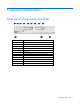
Item Description
15
Processor 1
16
System battery
17
SAS/SATA backplane power connector
18
Processor 2
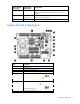
The symbols correspond to the symbols located on the interconnect bays. For more information, see the
HP ProLiant BL620c G7 Server Blade Installation Instructions that ship with the server blade.
System maintenance switch
The system maintenance switch (SW1) is an eight-position switch that is used for system configuration. The
default position for all eight positions is Off.
Position Description Function
S1
iLO 3 security Off = iLO 3 security is enabled.
On = iLO 3 security is disabled.
S2
Configuration
lock
Off = System configuration can be
changed.
On = System configuration is
locked.
S3
Reserved Reserved
S4
Reserved Reserved
S5
Password
protection
override
Off = No function
On = Clears power-on password
and administrator password
S6
Invalidate
configuration
Off = Normal
On = Clears NVRAM
S7
Reserved Reserved
S8
Reserved Reserved
System maintenance switch procedures
When you perform troubleshooting steps, this guide may instruct you to perform the following procedures:
• Clear the system configuration ("Clearing the system configuration" on page 10).
• Access the redundant ROM ("Accessing the redundant ROM" on page 11).
To complete these procedures, you must change physical settings on the system maintenance switch.
Clearing the system configuration
RBSU can be used to restore the factory default configuration. For more information, see "HP ROM-Based
Setup Utility (on page 68)." If the system is unable to boot into RBSU, use the following steps to clear the
system configuration:
1. Power down the server blade (on page 14).
2. Remove the server blade (on page 15).
3. Remove the access panel (on page 16).
4. Change position 6 of the system maintenance switch to on.