HP ProLiant BL620c G7 Server Blade User Guide Abstract This document is for the person who installs, administers, and troubleshoots servers and storage systems. HP assumes you are qualified in the servicing of computer equipment and trained in recognizing hazards in products with hazardous energy levels.
© Copyright 2010, 2011 Hewlett-Packard Development Company, L.P. The information contained herein is subject to change without notice. The only warranties for HP products and services are set forth in the express warranty statements accompanying such products and services. Nothing herein should be construed as constituting an additional warranty. HP shall not be liable for technical or editorial errors or omissions contained herein. Microsoft, Windows, and Windows Server are U.S.
Contents Component identification ............................................................................................................... 7 Front panel components and LEDs .................................................................................................................. 7 SAS and SATA hard drive LEDs ..................................................................................................................... 8 SAS and SATA hard drive LED combinations .........................
HP Memory Quarantine .................................................................................................................... 45 Online Spare memory population guidelines ....................................................................................... 45 Mirrored Memory population guidelines ............................................................................................. 46 Installing DIMMs ......................................................................................
Change control and proactive notification .......................................................................................... 79 Care Pack ....................................................................................................................................... 79 Troubleshooting .......................................................................................................................... 80 Troubleshooting resources ..........................................................
Technical support ...................................................................................................................... 108 Before you contact HP .............................................................................................................................. 108 HP contact information .............................................................................................................................. 108 Customer Self Repair ...........................................
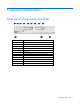
Component identification Front panel components and LEDs Item Description 1 UID LED 2 Health LED 3 Flex 1 LED 4 Flex 2 LED 5 Flex 3 LED 6 Flex 4 LED 7 Power On/Standby button and system power LED 8 Hard drive bay 1 9 Hard drive bay 2 10 Server release lever 11 Server release lever button 12 Local I/O connector Component identification 7
SAS and SATA hard drive LEDs Item Description 1 Fault/UID LED (amber/blue) 2 Online LED (green) SAS and SATA hard drive LED combinations Online/activity LED (green) Fault/UID LED (amber/blue) Interpretation On, off, or flashing Alternating amber and blue The drive has failed, or a predictive failure alert has been received for this drive; it also has been selected by a management application.
Online/activity LED (green) Fault/UID LED (amber/blue) Interpretation Off Steadily amber A critical fault condition has been identified for this drive, and the controller has placed it offline. Replace the drive as soon as possible. Off Amber, flashing regularly (1 Hz) A predictive failure alert has been received for this drive. Replace the drive as soon as possible. Off Off The drive is offline, a spare, or not configured as part of an array.
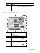
Item Description 15 Processor 1 16 System battery 17 SAS/SATA backplane power connector 18 Processor 2 The symbols correspond to the symbols located on the interconnect bays. For more information, see the HP ProLiant BL620c G7 Server Blade Installation Instructions that ship with the server blade. System maintenance switch The system maintenance switch (SW1) is an eight-position switch that is used for system configuration. The default position for all eight positions is Off.
5. Install the access panel (on page 16). 6. Install the server blade in the enclosure and power up the server blade. 7. Wait for the POST message that prompts you to change the switch setting: Maintenance switch detected in the "On" position. Power off the server and turn switch to the "Off" position. 8. Repeat steps 1 through 3. 9. Change position 6 of the system maintenance switch to off. 10. Repeat steps 5 and 6.
DIMM slot locations DIMM slots are numbered sequentially (1 through 16) for each processor. The supported AMP modes use the letter assignments for population guidelines.
Item Connector Description 1 Server blade For connecting to the SUV connector on the server blade front panel 2 Video For connecting a video monitor 3 USB For connecting up to two USB devices 4 Serial For trained personnel to connect a null modem serial cable and perform advanced diagnostic procedures Component identification 13
Operations Power up the server blade The Onboard Administrator initiates an automatic power-up sequence when the server blade is installed. If the default setting is changed, use one of the following methods to power up the server blade: • Use a virtual power button selection through iLO 3. • Press and release the Power On/Standby button. When the server blade goes from the standby mode to the full power mode, the system power LED changes from amber to green.
a. Select the Enclosure Information tab, and then select the Overall checkbox in the Device Bays item. b. Initiate a shutdown from the Virtual Power menu: — Select Momentary Press to initiate a controlled shutdown of applications and the OS. — Select Press and Hold to initiate an emergency shutdown of applications and the OS. IMPORTANT: When the server blade is in standby mode, auxiliary power is still being provided. To remove all power from the server blade, remove the server blade from the enclosure.
Remove the access panel To remove the component: 1. Power down the server blade (on page 14). 2. Remove the server blade (on page 15). 3. Press the access panel release button, and then slide the access panel to the rear. 4. Remove the access panel. WARNING: To reduce the risk of personal injury from hot surfaces, allow the drives and the internal system components to cool before touching them.
3. Remove the hard drive. To replace the component, reverse the removal procedure. Remove the left DIMM baffle To remove the component: 1. Power down the server blade (on page 14). 2. Remove the server blade (on page 15). 3. Remove the access panel (on page 16). 4. If installed, remove the battery pack (on page 19). You do not need to disconnect the cable from the battery. 5. Disconnect the SAS/SATA signal cable from the SAS backplane. 6. Unroute the SAS/SATA cable.
7. Remove the left DIMM baffle. Remove the right DIMM baffle To remove the component: 1. Power down the server blade (on page 14). 2. Remove the server blade (on page 15). 3. Remove the access panel (on page 16). 4. If installed, remove the battery pack (on page 19). You do not need to disconnect the cable from the battery. 5. Remove the right DIMM baffle.
Remove the front panel/hard drive cage assembly To remove the component: 1. Power down the server blade (on page 14). 2. Remove the server blade (on page 15). 3. Remove the access panel (on page 16). 4. Disconnect the signal cable and the power cable from the SAS backplane. 5. Loosen the thumbscrews. 6. Remove the front panel/hard drive cage assembly.
2. Remove the server blade (on page 15). 3. Remove the access panel (on page 16). 4. Do one of the following: o Remove the battery pack from the left DIMM baffle. o Remove the battery pack from the right DIMM baffle.
Setup Overview Installation of a server blade requires the following steps: 1. Install and configure an HP BladeSystem c-Class enclosure. 2. Install any server blade options. 3. Install interconnect modules in the enclosure. 4. Connect the interconnect modules to the network. 5. Install a server blade. 6. Complete the server blade configuration. Installing an HP BladeSystem c-Class enclosure Before performing any server blade-specific procedures, install an HP BladeSystem c-Class enclosure.
1. Remove the device bay blank. 2. Remove the three adjacent blanks. Removing a c7000 device bay divider 1. Slide the device bay shelf locking tab to the left to open it.
2. Push the device bay shelf back until it stops, lift the right side slightly to disengage the two tabs from the divider wall, and then rotate the right edge downward (clockwise). 3. Lift the left side of the device bay shelf to disengage the three tabs from the divider wall, and then remove it from the enclosure.
Removing a c3000 device bay mini-divider or device bay divider 1. Slide the locking tab down. 2. Remove the mini-divider or divider: o c3000 mini-divider: Push the divider toward the back of the enclosure until the divider drops out of the chassis. o c3000 divider: a. Push the divider toward the back of the enclosure until it stops. b. Slide the divider to the left to disengage the tabs from the wall. c. Rotate the divider clockwise.
d. Remove the divider from the enclosure. Creating a full-height device bay blank 1. 2. Obtain the coupler plate: o If you are using a device bay blank that came with the enclosure, the coupler plate can be found with the contents of the full-height device shipping box. o If you are using a device bay blank that you purchased as an option, remove the coupler plate from inside the blank.
3. Fit the slots on the bottom of the second blank on to the tabs on the coupler plate, and then slide the second blank forward until it snaps in place. 4. Install the full-height blank into the device bay. Installing interconnect modules For specific steps to install interconnect modules, see the documentation that ships with the interconnect module.
• HP BladeSystem c3000 Enclosure To support network connections for specific signals, install an interconnect module in the bay corresponding to the embedded adapter or mezzanine signals.
Two types of interconnect modules are available for HP BladeSystem c-Class enclosures: Pass-Thru modules and switch modules. For more information about interconnect module options, see the HP website (http://www.hp.com/go/bladesystem/interconnects). IMPORTANT: To connect to a network with a Pass-Thru module, always connect the Pass-Thru module to a network device that supports Gigabit speed.
2. Prepare the server blade for installation. 3. Install the server blade. Completing the configuration To complete the server blade and HP BladeSystem configuration, see the overview card that ships with the enclosure.
Hardware options installation Introduction If more than one option is being installed, read the installation instructions for all the hardware options and identify similar steps to streamline the installation process. WARNING: To reduce the risk of personal injury from hot surfaces, allow the drives and the internal system components to cool before touching them. CAUTION: To prevent damage to electrical components, properly ground the server before beginning any installation procedure.
CAUTION: The heatsink thermal interface media is not reusable and must be replaced if the heatsink is removed from the processor after it has been installed. IMPORTANT: Processor socket 1 must be populated at all times or the server blade does not function. To install the component: 1. Locate and download the latest ROM version from the HP website (http://www.hp.com/support). Follow the instructions on the website to update the system ROM. 2. Power down the server blade (on page 14). 3.
8. Open the processor locking lever and the processor socket retaining bracket. Do not remove the processor socket cover. IMPORTANT: Be sure the processor remains inside the processor installation tool. 9. If the processor has separated from the installation tool, carefully re-insert the processor in the tool. Handle the processor by the edges only, and do not touch the bottom of the processor, especially the contact area.
10. Align the processor installation tool with the socket, and then install the processor. THE PINS ON THE SYSTEM BOARD ARE VERY FRAGILE AND EASILY DAMAGED. CAUTION: THE PINS ON THE SYSTEM BOARD ARE VERY FRAGILE AND EASILY DAMAGED. To avoid damage to the system board: • Never install or remove a processor without using the processor installation tool. • Do not touch the processor socket contacts. • Do not tilt or slide the processor when lowering the processor into the socket.
11. Press the tabs on the processor installation tool to separate it from the processor, and then remove the tool. 12. Close the processor socket retaining bracket and the processor locking lever. The processor socket cover is automatically ejected. Remove the cover. CAUTION: Be sure to close the processor socket retaining bracket before closing the processor locking lever. The lever should close without resistance.
13. Remove the heatsink protective cover. CAUTION: Orient the heatsink as indicated in the procedure. Otherwise, you cannot install the hard drive cage. CAUTION: When tightening the heatsink screws, first tighten the front screw four to five turns, tighten the back screw completely, and then finish tightening the front screw. 14. Orient and install the heatsink. 15. Install the front panel/hard drive cage assembly. 16. Install the access panel (on page 16). 17.
Memory option Several DDR3 RDIMM option kits are available to expand server blade memory. The server blade supports dual-rank and quad-rank DIMMs. Server blades using Intel® Xeon® E7 family processors support up to 1 TB of memory using 32 x 32-GB DIMMs (16 DIMMs per processor). Server blades using Intel Xeon 6500 and 7500 series processors support up to 512 GB of memory using 32 x 16-GB DIMMs (16 DIMMs per processor).
supports the Intel Xeon E7 family processors. LV DIMMs are not supported on the HP ProLiant BL620c G7 Server Blade that uses the Intel Xeon 6500 and 7500 series processors. Dual- and quad-rank DIMMs To understand and configure memory protection modes properly, an understanding of dual- and quad-rank DIMMs is helpful. Some DIMM configuration requirements are based on these classifications. A single-rank DIMM has one set of memory chips that is accessed while writing to or reading from the memory.
Item Description Definition 6 DIMM type R = RDIMM (registered) E = UDIMM (unbuffered with ECC) For the latest supported memory information, see the QuickSpecs on the HP website (http://www.hp.com). DIMM installation guidelines Each supported processor contains two memory controllers per processor. Each memory controller can support up to eight DDR3 registered 1.5V DIMMs (RDIMMs) and 1.35V low voltage DIMMs (LV DIMMs).
• AMP modes Advanced ECC, DDDC, HP Memory Quarantine, Online Spare, and Mirrored Memory have further requirements beyond the ones listed here.
Channel Slot Slot number H 9 7 B F 16 15 8 D H 14 13 Memory architecture for processor 2 Channel Slot Slot number 1 B F 16 15 2 D H 14 13 3 B F 12 11 4 D H 10 9 5 A E 5 6 6 C G 7 8 7 A E 4 3 8 C G 2 1 Hardware options installation 40
Hemisphere mode The Intel® Xeon® E7 family and 6500/7500 series processor architectures incorporate Hemisphere mode, a high-performance interleaving technology. Hemisphere mode combines the tracking resources of both memory controllers within each processor for a more aggressive cache line pipelining. Hemisphere mode is enabled when processors in the system have identical DIMM populations behind both of their memory controllers.
The following illustration shows examples of Hemisphere mode and non-Hemisphere mode populations. The two non-Hemisphere examples show the following: • Each memory controller within a processor must have memory installed. • The DIMM configurations of each memory controller of a processor must be identical. Memory performance optimization The HP ProLiant BL620c G7 Server Blade supports up to 32 DIMMs installed on two multi-core processors.
• The best performance is obtained when all installed processors are enabled for Hemisphere mode. Hemisphere mode is optimum when four or eight DIMMs are installed per memory controller. Hemisphere mode can be achieved with two or six DIMMs per memory controller, but this configuration is not optimal for Hemisphere mode. • Maximum throughput is achieved when all DIMM slots are fully populated with the maximum number of eight quad-rank DIMMs per memory controller.
• Online Spare memory mode provides protection against persistent DRAM failure. Rank-sparing is more efficient than DIMM-sparing since only a portion of a DIMM is set aside for memory protection. For more information, see "Online Spare memory population guidelines (on page 45)." • Mirrored Memory mode provides the maximum protection against failed DIMMs. Uncorrectable errors in the DIMMs of one memory controller are corrected by the DIMMs in the mirrored memory controller.
HP Memory Quarantine The server blade is HP Memory Quarantine ready. The server blade will support this feature with a future planned firmware upgrade. The operating system must support this mode. HP Memory Quarantine increases the system availability by enabling the server and the operating system to work together to enable a server to recover from uncorrectable memory errors that would have otherwise caused a system crash. HP Memory Quarantine isolates the bad memory location before it affects other data.
Mirrored Memory population guidelines Errors that are not corrected by ECC, SDDC, or DDDC cannot be corrected by Online Spare memory. By providing added redundancy in the memory sub-system, Mirrored Memory provides the greatest protection against memory failure beyond ECC, SDDC, DDDC, and Online Spare memory. In Mirrored Memory mode, each Lockstep DIMM pair of a memory controller has a mirrored DIMM pair on the other memory controller of the same processor.
6. Install the DIMM. 7. Do one of the following: o Install the right DIMM baffle. o Install the left DIMM baffle. 8. Install the access panel (on page 16). 9. Install the server blade ("Installing a server blade" on page 28). 10. Power up the server blade (on page 14). Hot-plug SAS or SATA hard drive option IMPORTANT: To avoid improper operation, install only hot-plug hard drives in this server blade.
1. Remove the hard drive blank. 2. Prepare the hard drive.
3. Install the hard drive. 4. Determine the status of the hard drive from the hot-plug hard drive LEDs ("SAS and SATA hard drive LEDs" on page 8). 5. Resume normal server blade operations. Mezzanine card option Optional mezzanine cards provide additional I/O support. For mezzanine card locations, see "System board components (on page 9).
4. Remove the mezzanine connector cover. 5. Align the mezzanine connector on the optional mezzanine card with the mezzanine connector on the system board. CAUTION: To prevent damage to the server blade, apply pressure over the mezzanine connector when installing the mezzanine card. Do not apply pressure to the edges of the card. 6. Install the mezzanine card. Press down on the connector to seat the card. 7. Install the access panel (on page 16). 8.
Controller options The server blade ships with an embedded Smart Array P410i Controller. RAID 0 and 1 are supported and do not require a cache module to be installed. Upgrade options exist for the integrated array controller. For a list of supported options, see the QuickSpecs on the HP website (http://www.hp.com/support). The server blade supports both of the following options. You can install up to two cache modules in any combination.
CAUTION: To prevent a server blade malfunction or damage to the equipment, do not add or remove the battery pack while an array capacity expansion, RAID level migration, or stripe size migration is in progress. CAUTION: After the server blade is powered down, wait 15 seconds and then check the amber LED before unplugging the cable from the cache module. If the amber LED blinks after 15 seconds, do not remove the cable from the cache module.
6. Install the cache module. 7. Install the capacitor pack ("Installing a cache module" on page 51). 8. Install the server blade ("Installing a server blade" on page 28). 9. Power up the server blade (on page 14). Installing a capacitor pack CAUTION: To prevent a server blade malfunction or damage to the equipment, do not add or remove the battery pack while an array capacity expansion, RAID level migration, or stripe size migration is in progress.
6. Install the capacitor pack. 7. Install the server blade ("Installing a server blade" on page 28). 8. Power up the server blade (on page 14). HP Trusted Platform Module option Use these instructions to install and enable a TPM on a supported server blade. This procedure includes three sections: 1. Installing the Trusted Platform Module board. 2. Retaining the recovery key/password (on page 56). 3. Enabling the Trusted Platform Module (on page 56).
• Any attempt to remove an installed TPM from the system board breaks or disfigures the TPM security rivet. Upon locating a broken or disfigured rivet on an installed TPM, administrators should consider the system compromised and take appropriate measures to ensure the integrity of the system data. • When using BitLocker™, always retain the recovery key/password. The recovery key/password is required to enter Recovery Mode after BitLocker™ detects a possible compromise of system integrity.
6. Install the TPM security rivet by pressing the rivet firmly into the system board. 7. Install the access panel (on page 16). 8. Install the server blade ("Installing a server blade" on page 28). 9. Power up the server blade (on page 14). Retaining the recovery key/password The recovery key/password is generated during BitLocker™ setup, and can be saved and printed after BitLocker™ is enabled. When using BitLocker™, always retain the recovery key/password.
CAUTION: When a TPM is installed and enabled on the server blade, data access is locked if you fail to follow the proper procedures for updating the system or option firmware, replacing the system board, replacing a hard drive, or modifying OS application TPM settings. For more information on firmware updates and hardware procedures, see the HP Trusted Platform Module Best Practices White Paper on the HP website (http://www.hp.com/support).
Cabling Using the HP c-Class Blade SUV Cable The HP c-Class Blade SUV Cable enables the user to perform server blade administration, configuration, and diagnostic procedures by connecting video and USB devices directly to the server blade. For SUV cable connectors, see "HP c-Class Blade SUV Cable (on page 12).
4. Connect a USB keyboard to the second USB connector. Item Description 1 Monitor 2 USB mouse 3 HP c-Class Blade SUV Cable 4 Video connector 5 Server blade 6 USB keyboard Accessing local media devices Use the following configuration when configuring a server blade or loading software updates and patches from a USB CD/DVD-ROM or a USB diskette. 1. Connect the SUV cable to the server blade. 2. Connect the video connector to a monitor. 3. Connect a USB hub to one USB connector. 4.
Item Description 1 Monitor 2 USB mouse 3 HP c-Class Blade SUV Cable 4 Server blade 5 USB hub 6 USB keyboard 7 USB CD/DVD-ROM drive or diskette drive Cabling 60
Software and configuration utilities Server blade deployment tools HP BladeSystem c-Class Advanced management iLO 3 is a standard component of ProLiant c-Class server blades that provides server health and remote server blade manageability. Its features are accessed from a network client device using a supported web browser. In addition to other features, iLO 3 provides keyboard, mouse, and video (text and graphics) capability for a server blade, regardless of the state of the host OS or host server blade.
Deployment overview When a PXE-enabled target server blade boots, it obtains an IP address from a DHCP server. The target server blade obtains the name of the NBP from the appropriate boot server. Then, the target server blade uses TFTP to download the NBP from the boot server and executes the image. IMPORTANT: To connect to a network with a Pass-Thru module, always connect the Pass-Thru module to a network device that supports Gigabit speed.
• • o 64 MB of RAM o 64 MB of free hard drive space o 10-Mb/s network adapter PXE deployment server (storing boot images) o AMD Athlon™ XP processor (700 MHz or greater recommended), AMD Athlon™ 64 processor, or Intel® Pentium® III or higher processor (500 MHz recommended) o 256 MB of RAM o 10-Mb/s network adapter o CD-ROM drive Windows® repository server (Windows® or Linux deployment) o Windows® 2000 or Windows Server® 2003 OS installed o Network connection o CD-ROM drive o 1.
PXE deployment PXE enables server blades to load an image over the network from a PXE server, and then execute it in memory. The first NIC on the server blade is the default PXE boot NIC, but any of the other NC series NICs can be configured to boot PXE. For more information, see "Network-based PXE deployment (on page 61)." Actual NIC numeration depends on several factors, including the OS installed on the server blade.
• USB CD-ROM (on page 65) iLO virtual CD-ROM To deploy with a boot CD: 1. Do one of the following: o Insert the boot CD into the client PC using the iLO 3 Remote Console. o Use iLO 3 to create an image file of the boot CD. o Copy the image of the boot CD to a location on the network or the client PC hard drive. 2. Remotely access the server blade through iLO 3. See "HP BladeSystem c-Class advanced management (on page 61)." 3. Open Integrated Remote console or Java Remote console. 4.
Before beginning the deployment process, connect the server blade to the network. NOTE: For more information about hardware and cabling configurations, see the documents that ship with the enclosure. Two methods are available for diskette image deployment: • iLO virtual floppy (on page 66) • PXE ("PXE deployment" on page 64) Creating a boot diskette The SmartStart Scripting Toolkit provides the tools and information for creating a boot diskette.
• The server blade enclosure management module firmware is up-to-date. Refer to the HP Business Support Center website (http://www.hp.com/support). • The server blade is cabled properly to a supported SAN. • SAN storage drivers are loaded. Refer to supporting white papers and the HP website (http://www.hp.com/servers/rdp). For SAN configuration information for the server blade, refer to the HP StorageWorks SAN Design Reference Guide on the HP website (http://h18000.www1.hp.
HP ROM-Based Setup Utility RBSU is a configuration utility embedded in ProLiant servers that performs a wide range of configuration activities that can include the following: • Configuring system devices and installed options • Enabling and disabling system features • Displaying system information • Selecting the primary boot controller • Configuring memory options • Language selection For more information on RBSU, see the HP ROM-Based Setup Utility User Guide on the Documentation CD or the HP
Drives installed Drives used RAID level 1 1 RAID 0 2 2 RAID 1 3, 4, 5, or 6 3, 4, 5, or 6 RAID 5 More than 6 0 None To change any ORCA default settings and override the auto-configuration process, press the F8 key when prompted. For more information on RBSU, see the HP ROM-Based Setup Utility User Guide on the Documentation CD or the HP website (http://www.hp.com/support/smartstart/documentation). Boot options Near the end of the boot process, the boot options screen is displayed.
• RAID Memory Mode—Provides protection levels similar to Mirrored Memory Mode, and it requires less memory allocation than full redundancy. Configuring Advanced ECC memory To configure Advanced ECC memory: 1. Install the required DIMMs ("Installing DIMMs" on page 46). 2. When the prompt appears, access RBSU by pressing the F9 key during power-up. 3. Select System Options. 4. Select Advanced Memory Protection. 5. Select Advanced ECC Memory. 6. Press the Enter key. 7.
Configuring lockstep memory To configure Lockstep memory: 1. Install the required DIMMs ("Installing DIMMs" on page 46). 2. Access RBSU by pressing the F9 key during power-up when the prompt is displayed. 3. Select System Options. 4. Select Advanced Memory Protection. 5. Select Lockstep with Advanced ECC Support. 6. Press the Enter key. 7. Press the Esc key to exit the current menu, or press the F10 key to exit RBSU.
• Deleting a logical drive configuration • Setting the controller to be the boot controller If you do not use the utility, ORCA will default to the standard configuration. For more information regarding array controller configuration, refer to the controller user guide. For more information regarding the default configurations that ORCA uses, refer to the HP ROM-Based Setup Utility User Guide on the Documentation CD.
ROMPaq utility The ROMPaq utility enables you to upgrade the system firmware (BIOS). To upgrade the firmware, insert a ROMPaq USB Key into an available USB port and boot the system. In addition to ROMPaq, Online Flash Components for Windows and Linux operating systems are available for updating the system firmware. The ROMPaq utility checks the system and provides a choice (if more than one exists) of available firmware revisions.
Run the Erase Utility if you must erase the system for the following reasons: • You want to install a new operating system on a server blade with an existing operating system. • You encounter an error when completing the steps of a factory-installed operating system installation. To access the Erase Utility, use the System Erase button on the home screen of the SmartStart CD ("SmartStart software" on page 67).
External USB functionality HP provides external USB support to enable local connection of USB devices for server blade administration, configuration, and diagnostic procedures. For more information, see "Using the HP c-Class Blade SUV Cable (on page 58)." For additional security, external USB functionality can be disabled through RBSU. Disabling external USB support in RBSU disables the USB connectors on the HP c-Class Blade SUV Cable.
You can view recorded events in the IML in several ways, including the following: • From within HP SIM • From within operating system-specific IML viewers: o For Windows®: IML Viewer o For Linux: IML Viewer Application • From within the iLO 3 user interface • From within HP Insight Diagnostics (on page 75) • From within the Onboard Administrator GUI For more information, see the HP BladeSystem Onboard Administrator User Guide on the HP website (http://www.hp.com/go/bladesystem/documentation).
Keeping the system current Drivers IMPORTANT: Always perform a backup before installing or updating device drivers. The server blade includes new hardware that may not have driver support on all OS installation media. If you are installing a SmartStart-supported OS, use the SmartStart software (on page 67) and its Assisted Path feature to install the OS and latest driver support.
Operating System Version Support For information about specific versions of a supported operating system, refer to the operating system support matrix (http://www.hp.com/go/supportos). Firmware The Smart Update Firmware DVD is an organized firmware collection for ProLiant servers and options powered by HP Smart Update Manager (on page 78).
Change control and proactive notification HP offers Change Control and Proactive Notification to notify customers 30 to 60 days in advance of upcoming hardware and software changes on HP commercial products. For more information, refer to the HP website (http://www.hp.com/go/pcn). Care Pack HP Care Pack Services offer upgraded service levels to extend and expand bundled services with easy-to-buy, easy-to-use support packages that help you make the most of your server investments.
Troubleshooting Troubleshooting resources The HP ProLiant Servers Troubleshooting Guide provides procedures for resolving common problems and comprehensive courses of action for fault isolation and identification, error message interpretation, issue resolution, and software maintenance on ProLiant servers and server blades. This guide includes problem-specific flowcharts to help you navigate complex troubleshooting processes. To view the guide, select a language: • English (http://www.hp.
Important safety information Before servicing this product, read the Important Safety Information document provided with the server. Symbols on equipment The following symbols may be placed on equipment to indicate the presence of potentially hazardous conditions. This symbol indicates the presence of hazardous energy circuits or electric shock hazards. Refer all servicing to qualified personnel. WARNING: To reduce the risk of injury from electric shock hazards, do not open this enclosure.
WARNING: To reduce the risk of personal injury or damage to the equipment, be sure that: • • • • • The leveling feet are extended to the floor. The full weight of the rack rests on the leveling feet. The stabilizing feet are attached to the rack if it is a single-rack installation. The racks are coupled together in multiple-rack installations. Only one component is extended at a time. A rack may become unstable if more than one component is extended for any reason.
o HP recommends you have access to the server documentation for server-specific information. o HP recommends you have access to the SmartStart CD for value-added software and drivers required during the troubleshooting process. Download the current version of SmartStart from the HP website (http://www.hp.com/servers/smartstart).
Always use the recommended minimum configuration above before removing any processors. If you are unable to isolate the issue with the configuration above, you will then remove all but one of the additional processors. CAUTION: Before removing or replacing any processors, be sure to follow the guidelines provided in "Performing processor procedures in the troubleshooting process (on page 83).
do not provide a troubleshooting solution, follow the diagnostic steps in "General diagnosis flowchart (on page 86)." The General diagnosis flowchart is a generic troubleshooting process to be used when the problem is not server-specific or is not easily categorized into the other flowcharts.
General diagnosis flowchart The General diagnosis flowchart provides a generic approach to troubleshooting. If you are unsure of the problem, or if the other flowcharts do not fix the problem, use the following flowchart.
Item See 4 The most recent version of a particular server blade or option firmware is available on the HP Support website (http://www.hp.com/support). 5 "General memory problems are occurring" in the HP ProLiant Servers Troubleshooting Guide located on the Documentation CD or see "Troubleshooting resources (on page 80)" 6 • • 7 • • • Maintenance and service guides for p-Class server blades, located on the Documentation CD or the HP website (http://www.hp.
Server blade power-on problems flowchart Symptoms: • The server does not power on. • The system power LED is off or amber.
• The health LED is red or amber. NOTE: For the location of server LEDs and information on their statuses, refer to the server documentation.
POST problems flowchart Symptoms: • Server does not complete POST NOTE: The server has completed POST when the system attempts to access the boot device.
Item See 1 Server blade power-on problems flowchart (on page 88) 2 "POST error messages and beep codes (on page 96)" 3 "Video problems" in the HP ProLiant Servers Troubleshooting Guide located on the Documentation CD or see "Troubleshooting resources (on page 80)" 4 "General memory problems are occurring" in the HP ProLiant Servers Troubleshooting Guide located on the Documentation CD or see "Troubleshooting resources (on page 80)" 5 "Breaking the server down to the minimum hardware configuration
OS boot problems flowchart There are two ways to use SmartStart when diagnosing OS boot problems on a server blade: • Use iLO to remotely attach virtual devices to mount the SmartStart CD onto the server blade. • Use a local I/O cable and drive to connect to the server blade, and then restart the server blade.
Possible causes: • Corrupted OS • Hard drive subsystem problem • Incorrect boot order setting in RBSU Item See 1 HP ROM-Based Setup Utility User Guide (http://www.hp.
* See the server blade OS boot problems flowchart (on page 92) Server fault indications flowchart Symptoms: • Server boots, but a fault event is reported by Insight Management Agents • Server boots, but the internal health LED, external health LED, or component health LED is red or amber Troubleshooting 94
NOTE: For the location of server LEDs and information on their statuses, refer to the server documentation.
POST error messages and beep codes For a complete listing of error messages, refer to the "POST error messages" in the HP ProLiant Servers Troubleshooting Guide located on the Documentation CD or on the HP website (http://www.hp.com/support).
WARNING: To avoid potential problems, ALWAYS read the warnings and cautionary information in the server documentation before removing, replacing, reseating, or modifying system components.
Battery replacement If the server blade no longer automatically displays the correct date and time, you may need to replace the battery that provides power to the real-time clock. Under normal use, battery life is 5 to 10 years. WARNING: The computer contains an internal lithium manganese dioxide, a vanadium pentoxide, or an alkaline battery pack. A risk of fire and burns exists if the battery pack is not properly handled.
Regulatory compliance notices Regulatory compliance identification numbers For the purpose of regulatory compliance certifications and identification, this product has been assigned a unique regulatory model number. The regulatory model number can be found on the product nameplate label, along with all required approval markings and information. When requesting compliance information for this product, always refer to this regulatory model number.
radio communications. However, there is no guarantee that interference will not occur in a particular installation. If this equipment does cause harmful interference to radio or television reception, which can be determined by turning the equipment off and on, the user is encouraged to try to correct the interference by one or more of the following measures: • Reorient or relocate the receiving antenna. • Increase the separation between the equipment and receiver.
This Class A digital apparatus meets all requirements of the Canadian Interference-Causing Equipment Regulations. Cet appareil numérique de la classe A respecte toutes les exigences du Règlement sur le matériel brouilleur du Canada. Class B equipment This Class B digital apparatus meets all requirements of the Canadian Interference-Causing Equipment Regulations. Cet appareil numérique de la classe B respecte toutes les exigences du Règlement sur le matériel brouilleur du Canada.
This symbol on the product or on its packaging indicates that this product must not be disposed of with your other household waste. Instead, it is your responsibility to dispose of your waste equipment by handing it over to a designated collection point for the recycling of waste electrical and electronic equipment.
Class B equipment Chinese notice Class A equipment Laser compliance This product may be provided with an optical storage device (that is, CD or DVD drive) and/or fiber optic transceiver. Each of these devices contains a laser that is classified as a Class 1 Laser Product in accordance with US FDA regulations and the IEC 60825-1. The product does not emit hazardous laser radiation. Each laser product complies with 21 CFR 1040.10 and 1040.11 except for deviations pursuant to Laser Notice No.
For more information about battery replacement or proper disposal, contact an authorized reseller or an authorized service provider. Taiwan battery recycling notice The Taiwan EPA requires dry battery manufacturing or importing firms in accordance with Article 15 of the Waste Disposal Act to indicate the recovery marks on the batteries used in sales, giveaway or promotion. Contact a qualified Taiwanese recycler for proper battery disposal.
Japanese notices Taiwan notices Regulatory compliance notices 105
Electrostatic discharge Preventing electrostatic discharge To prevent damaging the system, be aware of the precautions you need to follow when setting up the system or handling parts. A discharge of static electricity from a finger or other conductor may damage system boards or other static-sensitive devices. This type of damage may reduce the life expectancy of the device. To prevent electrostatic damage: • Avoid hand contact by transporting and storing products in static-safe containers.
Specifications Environmental specifications Specification Value — Temperature range* Operating 10°C to 35°C (50°F to 95°F) Non-operating -30°C to 60°C (-22°F to 140°F) Relative humidity (noncondensing)** — Operating 10% to 90% @ 28°C (82.4°F) Non-operating 5% to 95% @ 38.7°C (101.7°F) Altitude† — Operating 3050 m (10,000 ft) Non-operating 9144 m (30,000 ft) * The following temperature conditions and limitations apply: - All temperature ratings shown are for sea level.
Technical support Before you contact HP Be sure to have the following information available before you call HP: • Technical support registration number (if applicable) • Product serial number • Product model name and number • Product identification number • Applicable error messages • Add-on boards or hardware • Third-party hardware or software • Operating system type and revision level HP contact information For the name of the nearest HP authorized reseller: • See the Contact HP worldwi
• Optional—Parts for which customer self repair is optional. These parts are also designed for customer self repair. If, however, you require that HP replace them for you, there may or may not be additional charges, depending on the type of warranty service designated for your product. NOTE: Some HP parts are not designed for customer self repair. In order to satisfy the customer warranty, HP requires that an authorized service provider replace the part.
Riparazione da parte del cliente Per abbreviare i tempi di riparazione e garantire una maggiore flessibilità nella sostituzione di parti difettose, i prodotti HP sono realizzati con numerosi componenti che possono essere riparati direttamente dal cliente (CSR, Customer Self Repair). Se in fase di diagnostica HP (o un centro di servizi o di assistenza HP) identifica il guasto come riparabile mediante un ricambio CSR, HP lo spedirà direttamente al cliente per la sostituzione.
CSR-Teile werden abhängig von der Verfügbarkeit und vom Lieferziel am folgenden Geschäftstag geliefert. Für bestimmte Standorte ist eine Lieferung am selben Tag oder innerhalb von vier Stunden gegen einen Aufpreis verfügbar. Wenn Sie Hilfe benötigen, können Sie das HP technische Support Center anrufen und sich von einem Mitarbeiter per Telefon helfen lassen. Den Materialien, die mit einem CSR-Ersatzteil geliefert werden, können Sie entnehmen, ob das defekte Teil an HP zurückgeschickt werden muss.
Para obtener más información acerca del programa de Reparaciones del propio cliente de HP, póngase en contacto con su proveedor de servicios local. Si está interesado en el programa para Norteamérica, visite la página web de HP siguiente (http://www.hp.com/go/selfrepair). Customer Self Repair Veel onderdelen in HP producten zijn door de klant zelf te repareren, waardoor de reparatieduur tot een minimum beperkt kan blijven en de flexibiliteit in het vervangen van defecte onderdelen groter is.
Opcional – Peças cujo reparo feito pelo cliente é opcional. Essas peças também são projetadas para o reparo feito pelo cliente. No entanto, se desejar que a HP as substitua, pode haver ou não a cobrança de taxa adicional, dependendo do tipo de serviço de garantia destinado ao produto. OBSERVAÇÃO: Algumas peças da HP não são projetadas para o reparo feito pelo cliente. A fim de cumprir a garantia do cliente, a HP exige que um técnico autorizado substitua a peça.
Technical support 114
Technical support 115
Acronyms and abbreviations ACU Array Configuration Utility AES-NI advanced encryption standard new instructions AMP Advanced Memory Protection ASR Automatic Server Recovery BBWC battery-backed write cache BMC baseboard management controller CSR Customer Self Repair DDDC Double Device Data Correction ESD electrostatic discharge FBWC flash-backed write cache IEC International Electrotechnical Commission iLO 3 Integrated Lights-Out 3 Acronyms and abbreviations 116
IML Integrated Management Log KVM keyboard, video, and mouse LV DIMM Low voltage DIMM NUMA Non-Uniform Memory Architecture ORCA Option ROM Configuration for Arrays POST Power-On Self Test PSP ProLiant Support Pack PXE Preboot Execution Environment QPI QuickPath Interconnect RBSU ROM-Based Setup Utility RPM Red Hat Package Manager SAS serial attached SCSI SATA serial ATA SD Secure Digital Acronyms and abbreviations 117
SDDC Single Device Data Correction SDHC Secure Digital High-Capacity SIM Systems Insight Manager SMB scalable memory buffer SMI scalable memory interconnect SUV serial, USB, video TPM trusted platform module TXT trusted execution technology UID unit identification USB universal serial bus VCA Version Control Agent Acronyms and abbreviations 118
Index A access panel 16 accessing a server blade with local KVM 58, 59 ACU (Array Configuration Utility) 71 additional information 80 Advanced ECC memory 69, 70 Advanced ECC population guidelines 44 AMP (Advanced Memory Protection) 69 AMP modes 69 Array Configuration Utility (ACU) 71 ASR (Automatic Server Recovery) 72 authorized reseller 108 auto-configuration process 68 Automatic Server Recovery (ASR) 72 B Basic Input/Output System (BIOS) 69, 73 batteries, replacing 98, 103 battery 98, 103 battery disposa
DIMMs, dual-rank 37 DIMMs, installation 46 DIMMs, quad-rank 37 disposal, battery 101, 103 disposal, waste 101 Double Device Data Correction (DDDC) downloading files 108 drive cage, removing 18 drivers 61, 77 drives, determining status of 8 drives, installing 47 44 E electrostatic discharge 106 enabling the Trusted Platform Module 56 enabling, Trusted Platform Module (TPM) 56 enclosure, installing 21 environmental specifications 107 Erase Utility 73 error messages 96 error messages, POST 96 European Union
internal internal internal internal health LED 8 SD support 75 USB connector 10 USB functionality 74, 75 O online spare memory 45, 69 operating system version support 78 operating systems 78 operating systems supported 78 operations 14 Option ROM Configuration for Arrays (ORCA) options 28 options installation 28, 30 ORCA (Option ROM Configuration for Arrays) OS boot problems flowchart 92 overview 21 J Japanese notice 102, 105 K Korean notices 102 L laser compliance 103 laser devices 103 LED, health 8
removing the access panel 16 removing the server blade 15 required information 108 resources 66, 80 resources, troubleshooting 80 retaining the recovery key/password 56 right DIMM baffle, removing 18 ROM legacy USB support 74 ROM redundancy 11, 74 ROM-Based Setup Utility (RBSU) 56, 68 ROMPaq utility 73, 74 S safety considerations 80 safety information 74 SAN configuration 71 SAS drives 8 SAS hard drive LEDs 8 SATA hard drive 8 SATA hard drive LEDs 8 scripted installation 67 SD support 75 serial connector 1
website, HP 108 wireless devices 104, 105 Index 123