
User guide
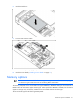
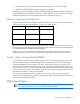
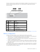

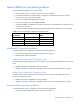
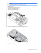
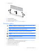
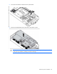
Table Of Contents
- HP ProLiant BL490c G7 Server Blade User Guide
- Abstract
- Notice
- Contents
- Component identification
- Operations
- Setup
- Hardware options installation
- Introduction
- Hard drive option
- Memory options
- Processor option
- Mezzanine card option
- HP Trusted Platform Module option
- Cabling
- Software and configuration utilities
- Troubleshooting
- Battery replacement
- Regulatory compliance notices
- Regulatory compliance identification numbers
- Federal Communications Commission notice
- Declaration of conformity for products marked with the FCC logo, United States only
- Modifications
- Cables
- Canadian notice (Avis Canadien)
- European Union regulatory notice
- Disposal of waste equipment by users in private households in the European Union
- Japanese notice
- BSMI notice
- Korean notice
- Chinese notice
- Laser compliance
- Battery replacement notice
- Taiwan battery recycling notice
- Acoustics statement for Germany (Geräuschemission)
- Electrostatic discharge
- Specifications
- Technical support
- Acronyms and abbreviations
- Index
Hardware options installation 27
• Observe the general DIMM slot population guidelines (on page 25).
• Always install DIMMs in channels 1 and 2 for each installed processor.
• Do not install DIMMs in channel 3 for any processor.
• DIMM configuration on channel 1 and channel 2 of a processor must be identical.
• In multi-processor configurations, each processor must have a valid Lockstep Memory configuration.
• In multi-processor configurations, each processor may have a different valid Lockstep Memory
configuration.
Single-processor Lockstep population order
For Lockstep memory mode configurations with a single processor, populate the DIMM slots in the following
order:
• RDIMM
o First: A and B
o Next: D and E
o Last: G and H
o Do not populate slots C, F, or I.
• UDIMM
o First: A and B
o Last: D and E
o Do not populate slots C, F, G, H, or I.
After installing the DIMMs, use RBSU to configure the system for Lockstep memory support ("Configuring
lockstep memory" on page 52).
Multi-processor Lockstep population order
For Lockstep memory mode configurations with multiple processors, populate the DIMM slots for each
processor in the following order:
• RDIMM
o First: A and B
o Next: D and E
o Last: G and H
o Do not populate slots C, F, or I.
• UDIMM
o First: A and B
o Last: D and E
o Do not populate slots C, F, G, H, or I.
After installing the DIMMs, use RBSU to configure the system for Lockstep memory support ("Configuring
lockstep memory" on page 52).
Installing DIMMs