HP ProLiant BL490c G7 Server Blade User Guide Abstract This document is for the person who installs, administers, and troubleshoots servers and storage systems. HP assumes you are qualified in the servicing of computer equipment and trained in recognizing hazards in products with hazardous energy levels.
© Copyright 2010, 2011 Hewlett-Packard Development Company, L.P. The information contained herein is subject to change without notice. The only warranties for HP products and services are set forth in the express warranty statements accompanying such products and services. Nothing herein should be construed as constituting an additional warranty. HP shall not be liable for technical or editorial errors or omissions contained herein. Microsoft, Windows, and Windows Server are U.S.
Contents Component identification ............................................................................................................... 6 Front panel components ............................................................................................................................. 6 Front panel LEDs ....................................................................................................................................... 6 System board components ..................................
Accessing a server blade with local media devices ............................................................................ 41 Software and configuration utilities ............................................................................................... 43 Server blade deployment tools .................................................................................................................. 43 HP BladeSystem c-Class Advanced management ......................................................
Battery replacement .................................................................................................................... 78 Regulatory compliance notices ..................................................................................................... 79 Regulatory compliance identification numbers ............................................................................................. 79 Federal Communications Commission notice ......................................................
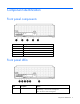
Component identification Front panel components Item Description 1 HP c-Class Blade SUV Cable connector 2 Serial label pull tab 3 Release button 4 Power On/Standby button 5 Server blade release lever Front panel LEDs Item Description Status 1 UID LED Blue = Identified Blue flashing = Active remote management Off = No active remote management Component identification 6
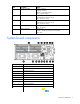
Item Description Status 2 Internal health LED Green = Normal Flashing = Booting Amber = Degraded condition Red = Critical condition 3 Flex 1 LED Green = Network linked Green flashing = Network activity Off = No link or activity 4 Flex 2 LED Green = Network linked Green flashing = Network activity Off = No link or activity 5 Hard drive activity LED Green = Activity Off = No activity 6 System power LED Green = On Amber = Standby (auxiliary power available) Off = Off System board components
Item Description 13 TPM connector 14 System maintenance switch 15 Processor socket 2 16 Processor socket 1 The symbols correspond to the symbols located on the interconnect bays. For more information, see the HP ProLiant BL490c G7 Server Blade Installation Instructions that ship with the server blade.
5. Install the access panel (on page 13). 6. Install the server blade in the enclosure and power up the server blade. 7. Wait for the POST message that prompts you to change the switch setting: Maintenance switch detected in the "On" position. Power off the server and turn switch to the "Off" position. 8. Repeat steps 1 through 3. 9. Change position 6 of the system maintenance switch to off. 10. Repeat steps 5 and 6.
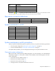
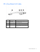
HP c-Class Blade SUV Cable Item Connector Description 1 Server blade For connecting to the SUV connector on the server blade front panel 2 Video For connecting a video monitor 3 USB For connecting up to two USB devices 4 Serial For trained personnel to connect a null modem serial cable and perform advanced diagnostic procedures Component identification 10
Operations Power up the server blade The HP BladeSystem Onboard Administrator initiates an automatic power-up sequence when the server blade is installed. If the default setting is changed, use one of the following methods to power up the server blade: • Use a virtual power button selection through iLO 3. • Press and release the Power On/Standby button. When the server blade goes from the standby mode to the full power mode, the system power LED changes from amber to green.
• Use the HP BladeSystem Onboard Administrator GUI to initiate a shutdown: a. Select the Enclosure Information tab, and then select the Overall checkbox in the Device Bays item. b. Initiate a shutdown from the Virtual Power menu: — Select Momentary Press to initiate a controlled shutdown of applications and the OS. — Select Press and Hold to initiate an emergency shutdown of applications and the OS. IMPORTANT: When the server blade is in standby mode, auxiliary power is still being provided.
Remove the access panel To remove the component: 1. Power down the server blade (on page 11). 2. Remove the server blade (on page 12). 3. Press the access panel release button. 4. Slide the access panel towards the rear of the server blade, and then lift to remove the panel. Install the access panel 1. Place the access panel on top of the server blade. 2. Slide the access panel forward until it clicks into place.
Setup Overview To install a server blade, complete the following steps: 1. Install and configure an HP BladeSystem c-Class enclosure. 2. Install any server blade options. 3. Install interconnect modules in the enclosure. 4. Connect the interconnect modules to the network. 5. Install a server blade. 6. Complete the server blade configuration. Installing an HP BladeSystem c-Class enclosure Before performing any server blade-specific procedures, install an HP BladeSystem c-Class enclosure.
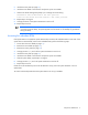
Interconnect bay numbering and device mapping • HP BladeSystem c7000 Enclosure To support network connections for specific signals, install an interconnect module in the bay corresponding to the embedded NIC or mezzanine signals.
• HP BladeSystem c3000 Enclosure and Tower Enclosure Server blade signal Interconnect bay number Interconnect bay label Notes Flex adapter 1, 2 (embedded) 1 — Mezzanine 1 2 Four port cards connect to bay 2. Mezzanine 2 3 and 4 • • • Four port cards Ports 1 and 3 connect to bay 3. Ports 2 and 4 connect to bay 4.
Connecting to the network To connect the HP BladeSystem to a network, each enclosure must be configured with network interconnect devices to manage signals between the server blades and the external network. Two types of interconnect modules are available for HP BladeSystem c-Class enclosures: Pass-thru modules and switch modules. For more information about interconnect module options, see the HP website (http://www.hp.com/go/bladesystem/interconnects).
2. Remove the enclosure connector cover. 3. Prepare the server blade for installation.
4. Install the server blade. Completing the configuration To complete the server blade and HP BladeSystem configuration, see the overview card that ships with the enclosure.
Hardware options installation Introduction If more than one option is being installed, read the installation instructions for all the hardware options and identify similar steps to streamline the installation process. WARNING: To reduce the risk of personal injury from hot surfaces, allow the drives and the internal system components to cool before touching them. CAUTION: To prevent damage to electrical components, properly ground the server before beginning any installation procedure.
5. Install the hard drive. 6. Connect and route the cables. 7. Install the access panel (on page 13). 8. Install the server blade ("Installing a server blade" on page 17). Memory options IMPORTANT: This server blade does not support mixing RDIMMs and UDIMMs. Attempting to mix these two types causes the server to halt during BIOS initialization. The memory subsystem in this server blade can support RDIMMs or UDIMMs. Both types are referred to as DIMMs when the information applies to both types.
• Single- and dual-rank PC3-10600 (DDR-1333) DIMMs operating at 1333 and 1066 MHz • Quad-rank PC3-8500 (DDR-1067) DIMMs operating at 1066 MHz Depending on the processor model, the number of DIMMs installed, and whether UDIMMs or RDIMMs are installed, the memory clock speed may be reduced to 1066 or 800 MHz. For more information on the effect of DIMM slot population, see "General DIMM slot population guidelines (on page 25).
The memory subsystem may be populated with either RDIMMs or UDIMMs, but mixing the two types is not supported. To determine DIMM characteristics, use the label attached to the DIMM and the following illustration and table.
For the latest memory configuration information, see the QuickSpecs on the HP website (http://www.hp.com). RDIMM maximum memory configurations The following table lists the maximum memory configuration possible with 8-GB RDIMMs.
General DIMM slot population guidelines Observe the following guidelines for all AMP modes: • Populate DIMM slots for a processor only if the processor is installed. • To maximize performance in multi-processor configurations, distribute the total memory capacity between all processors as evenly as possible. • Do not mix Unbuffered and Registered PC3 DIMMs. • Each channel supports up to two Unbuffered DIMMs.
• Always install DIMMs in channels 1 and 2 for each installed processor. • Do not install DIMMs in channel 3 for any processor. • DIMMs installed on channel 1 and channel 2 of an installed processor must be identical. • In multi-processor configurations, each processor must have a valid Mirrored Memory configuration. • In multi-processor configurations, each processor may have a different valid Mirrored Memory configuration.
• Observe the general DIMM slot population guidelines (on page 25). • Always install DIMMs in channels 1 and 2 for each installed processor. • Do not install DIMMs in channel 3 for any processor. • DIMM configuration on channel 1 and channel 2 of a processor must be identical. • In multi-processor configurations, each processor must have a valid Lockstep Memory configuration. • In multi-processor configurations, each processor may have a different valid Lockstep Memory configuration.
WARNING: To reduce the risk of personal injury from hot surfaces, allow the drives and the internal system components to cool before touching them. To install the component: 1. Power down the server blade (on page 11). 2. Remove the server blade (on page 12). 3. Remove the access panel (on page 13). 4. Disconnect the hard drive cables. 5. Remove the DIMM baffle with the hard drives and cables in place. 6. Open the DIMM slot latches.
7. Install the DIMM. 8. Install the DIMM baffle. 9. Connect the hard drive cables. 10. Install the access panel (on page 13). 11. Install the server blade ("Installing a server blade" on page 17). Processor option WARNING: To reduce the risk of personal injury from hot surfaces, allow the drives and the internal system components to cool before touching them.
5. Disconnect the hard drive cables from the system board. 6. Remove the DIMM baffle with the hard drives and cables in place. CAUTION: Failure to completely open the processor locking lever prevents the processor from seating during installation, leading to hardware damage.
7. Open the processor locking lever and the processor socket retaining bracket. Do not remove the processor socket cover. IMPORTANT: Be sure the processor remains inside the processor installation tool. 8. If the processor has separated from the installation tool, carefully re-insert the processor in the tool. Handle the processor by the edges only, and do not touch the bottom of the processor, especially the contact area.
9. Align the processor installation tool with the socket, and then install the processor. THE PINS ON THE SYSTEM BOARD ARE VERY FRAGILE AND EASILY DAMAGED. CAUTION: THE PINS ON THE SYSTEM BOARD ARE VERY FRAGILE AND EASILY DAMAGED. To avoid damage to the system board: • Never install or remove a processor without using the processor installation tool. • Do not touch the processor socket contacts. • Do not tilt or slide the processor when lowering the processor into the socket.
10. Press the tabs on the processor installation tool to separate it from the processor, and then remove the tool. 11. Close the processor socket retaining bracket and the processor locking lever. The processor socket cover is automatically ejected. Remove the cover. CAUTION: Be sure to close the processor socket retaining bracket before closing the processor locking lever. The lever should close without resistance.
12. Remove the thermal interface media protective cover. CAUTION: To avoid damage to the system board, processor socket, and screws, do not overtighten the heatsink screws. Use the wrench supplied with the system to reduce the possibility of overtightening the screws. CAUTION: To avoid possible thermal damage, install replacement heatsinks as indicated on the heatsink labels. The heatsinks are not interchangeable between processor 1 and processor 2 within a server blade. 13. Install the heatsink.
Mezzanine card option Optional mezzanine cards are classified as Type I mezzanine cards and Type II mezzanine cards. The card type determines where it can be installed in the server blade. • Install Type I mezzanine cards on either mezzanine 1 connector or mezzanine 2 connector. • Install Type II mezzanine cards only on mezzanine 2 connector. Optional mezzanine cards enable network connectivity and provide Fibre Channel support. For mezzanine card locations, see the system board components (on page 7).
5. Install the mezzanine card. Press down on the connector to seat the board. 6. Install the access panel (on page 13). 7. Install the server blade ("Installing a server blade" on page 17). HP Trusted Platform Module option Use these instructions to install and enable a TPM on a supported server blade. This procedure includes three sections: 1. Installing the Trusted Platform Module board (on page 37). 2. Retaining the recovery key/password (on page 38). 3.
• Any attempt to remove an installed TPM from the system board breaks or disfigures the TPM security rivet. Upon locating a broken or disfigured rivet on an installed TPM, administrators should consider the system compromised and take appropriate measures to ensure the integrity of the system data. • When using BitLocker™, always retain the recovery key/password. The recovery key/password is required to enter Recovery Mode after BitLocker™ detects a possible compromise of system integrity.
6. Install the TPM security rivet by pressing the rivet firmly into the system board. 7. Install the access panel (on page 13). 8. Install the server blade ("Installing a server blade" on page 17). 9. Power up the server blade (on page 11). Retaining the recovery key/password The recovery key/password is generated during BitLocker™ setup, and can be saved and printed after BitLocker™ is enabled. When using BitLocker™, always retain the recovery key/password.
CAUTION: When a TPM is installed and enabled on the server blade, data access is locked if you fail to follow the proper procedures for updating the system or option firmware, replacing the system board, replacing a hard drive, or modifying OS application TPM settings. For more information on firmware updates and hardware procedures, see the HP Trusted Platform Module Best Practices White Paper on the HP website (http://www.hp.com/support).
Cabling Hard drive cabling CAUTION: When routing cables, always be sure that the cables are not in a position where they can be pinched or crimped. Using the HP c-Class Blade SUV Cable The HP c-Class Blade SUV Cable enables the user to perform server blade administration, configuration, and diagnostic procedures by connecting video and USB devices directly to the server blade. For SUV cable connectors, see "HP c-Class Blade SUV Cable (on page 10).
Numerous configurations are possible. This section offers two possible configurations. For more information, see "USB support and functionality (on page 55)." Accessing a server blade with local KVM For this configuration, a USB hub is not necessary. To connect additional devices, use a USB hub. CAUTION: Before disconnecting the SUV cable from the connector, always squeeze the release buttons on the sides of the connector. Failure to do so can result in damage to the equipment. 1.
3. Connect a USB hub to one USB connector. 4.
Software and configuration utilities Server blade deployment tools HP BladeSystem c-Class Advanced management iLO 3 is a standard component of ProLiant c-Class server blades that provides server health and remote server blade manageability. Its features are accessed from a network client device using a supported web browser. In addition to other features, iLO 3 provides keyboard, mouse, and video (text and graphics) capability for a server blade, regardless of the state of the host OS or host server blade.
Deployment overview When a PXE-enabled target server blade boots, it obtains an IP address from a DHCP server. The target server blade obtains the name of the NBP from the appropriate boot server. Then, the target server blade uses TFTP to download the NBP from the boot server and executes the image. IMPORTANT: To connect to a network with a Pass-Thru module, always connect the Pass-Thru module to a network device that supports Gigabit speed.
• • o 64 MB of RAM o 64 MB of free hard drive space o 1-Gb/s network adapter or greater PXE deployment server (storing boot images) o AMD Athlon™ XP processor (2.0 GHz or greater recommended), AMD Athlon™ 64 processor, or Intel® Pentium® III or higher processor (2.0 GHz or greater recommended) o 2 GB of RAM o 1-Gb/s network adapter o CD-ROM drive Windows® repository server (Windows® or Linux deployment) o Windows Server® 2003 OS installed o Network connection o CD-ROM drive o 1.
PXE deployment PXE enables server blades to load an image over the network from a PXE server, and then execute it in memory. The first NIC on the server blade is the default PXE boot NIC, but any of the other NC series NICs can be configured to boot PXE. For more information, see "Network-based PXE deployment (on page 43)." Actual NIC numeration depends on several factors, including the OS installed on the server blade.
• USB CD-ROM (on page 47) iLO virtual CD-ROM To deploy with a boot CD: 1. Do one of the following: o Insert the boot CD into the client PC using the iLO 3 Remote Console. o Use iLO 3 to create an image file of the boot CD. o Copy the image of the boot CD to a location on the network or the client PC hard drive. 2. Remotely access the server blade through iLO 3. See "HP BladeSystem c-Class advanced management (on page 43)." 3. Open Integrated Remote console or Java Remote console. 4.
Creating a boot diskette The SmartStart Scripting Toolkit provides the tools and information for creating a boot diskette. For details, refer to the SmartStart Scripting Toolkit User Guide and download the latest version of the software from the HP website (http://www.hp.com/servers/sstoolkit). As an alternative method, configure the hardware manually with RBSU and the iLO 3 remote console. With this method, the disk is more generic and integrates with an existing network OS installation process.
For SAN configuration information for the server blade, refer to the HP StorageWorks SAN Design Reference Guide on the HP website (http://h18000.www1.hp.com/products/storageworks/san/documentation.html). Configuration tools SmartStart software SmartStart is a collection of software that optimizes single-server setup, providing a simple and consistent way to deploy server configuration. SmartStart has been tested on many ProLiant server products, resulting in proven, reliable configurations.
• Selecting the primary boot controller • Configuring memory options • Language selection For more information on RBSU, see the HP ROM-Based Setup Utility User Guide on the Documentation CD or the HP website (http://www.hp.com/support/smartstart/documentation). Using RBSU To use RBSU, use the following keys: • To access RBSU, press the F9 key during power-up when prompted. • To navigate the menu system, use the arrow keys. • To make selections, press the Enter key.
For more information on RBSU, see the HP ROM-Based Setup Utility User Guide on the Documentation CD or the HP website (http://www.hp.com/support/smartstart/documentation). Boot options Near the end of the boot process, the boot options screen is displayed. This screen is visible for several seconds before the system attempts to boot from a supported boot device. During this time, you can do the following: • Access RBSU by pressing the F9 key.
7. Press the Esc key to exit the current menu or press the F10 key to exit RBSU. For more information on mirrored memory, see the white paper on the HP website (http://h18000.www1.hp.com/products/servers/technology/memoryprotection.html). Configuring lockstep memory To configure Lockstep memory: 1. Install the required DIMMs ("Installing DIMMs" on page 27). 2. Access RBSU by pressing the F9 key during power-up when the prompt is displayed. 3. Select System Options. 4.
The utility also provides support for the following functions: • Reconfiguring one or more logical drives • Viewing the current logical drive configuration • Deleting a logical drive configuration • Setting the controller to be the boot controller If you do not use the utility, ORCA will default to the standard configuration. For more information regarding array controller configuration, refer to the controller user guide.
ASR increases server availability by restarting the server within a specified time after a system hang or shutdown. At the same time, the HP SIM console notifies you by sending a message to a designated pager number that ASR has restarted the system. You can disable ASR from the HP SIM console or through RBSU. ROMPaq utility The ROMPaq utility enables you to upgrade the system firmware (BIOS). To upgrade the firmware, insert a ROMPaq USB Key into an available USB port and boot the system.
CAUTION: Perform a backup before running the System Erase Utility. The utility sets the system to its original factory state, deletes the current hardware configuration information, including array setup and disk partitioning, and erases all connected hard drives completely. Refer to the instructions for using this utility. Run the Erase Utility if you must erase the system for the following reasons: • You want to install a new operating system on a server blade with an existing operating system.
Internal USB functionality An internal USB connector is available for use with security key devices and USB drive keys. This solution provides for use of a permanent USB key installed in the internal connector, avoiding issues of clearance on the front of the rack and physical access to secure data. External USB functionality HP provides external USB support to enable local connection of USB devices for server blade administration, configuration, and diagnostic procedures.
Integrated Management Log The IML records hundreds of events and stores them in an easy-to-view form. The IML timestamps each event with 1-minute granularity.
Keeping the system current Drivers IMPORTANT: Always perform a backup before installing or updating device drivers. The server blade includes new hardware that may not have driver support on all OS installation media. If you are installing a SmartStart-supported OS, use the SmartStart software (on page 49) and its Assisted Path feature to install the OS and latest driver support.
• Offline, automatic mode for HP ProLiant BL, DL, ML, and 100 Series servers • Firmware deployment support for HP ProLiant 100 Series servers HP Smart Update Manager The HP Smart Update Manager provides intelligent and flexible firmware and software deployment. This technology assists in reducing the complexity of provisioning and updating HP ProLiant Servers, options, and Blades within the datacenter. HP SUM is delivered on The Smart Update Firmware DVD, ProLiant Support Packs, and Easy Set-up CDs.
Troubleshooting Troubleshooting resources The HP ProLiant Servers Troubleshooting Guide provides procedures for resolving common problems and comprehensive courses of action for fault isolation and identification, error message interpretation, issue resolution, and software maintenance on ProLiant servers and server blades. This guide includes problem-specific flowcharts to help you navigate complex troubleshooting processes. To view the guide, select a language: • English (http://www.hp.
Important safety information Before servicing this product, read the Important Safety Information document provided with the server. Symbols on equipment The following symbols may be placed on equipment to indicate the presence of potentially hazardous conditions. This symbol indicates the presence of hazardous energy circuits or electric shock hazards. Refer all servicing to qualified personnel. WARNING: To reduce the risk of injury from electric shock hazards, do not open this enclosure.
WARNING: To reduce the risk of personal injury or damage to the equipment, be sure that: • • • • • The leveling feet are extended to the floor. The full weight of the rack rests on the leveling feet. The stabilizing feet are attached to the rack if it is a single-rack installation. The racks are coupled together in multiple-rack installations. Only one component is extended at a time. A rack may become unstable if more than one component is extended for any reason.
o HP recommends you have access to the server documentation for server-specific information. o HP recommends you have access to the SmartStart CD for value-added software and drivers required during the troubleshooting process. Download the current version of SmartStart from the HP website (http://www.hp.com/servers/smartstart).
Always use the recommended minimum configuration above before removing any processors. If you are unable to isolate the issue with the configuration above, you will then remove all all but one of the additional processors. CAUTION: Before removing or replacing any processors, be sure to follow the guidelines provided in "Performing processor procedures in the troubleshooting process (on page 63).
do not provide a troubleshooting solution, follow the diagnostic steps in "General diagnosis flowchart (on page 66)." The General diagnosis flowchart is a generic troubleshooting process to be used when the problem is not server-specific or is not easily categorized into the other flowcharts.
General diagnosis flowchart The General diagnosis flowchart provides a generic approach to troubleshooting. If you are unsure of the problem, or if the other flowcharts do not fix the problem, use the following flowchart.
Item See 4 The most recent version of a particular server blade or option firmware is available on the HP Support website (http://www.hp.com/support). 5 "General memory problems are occurring" in the HP ProLiant Servers Troubleshooting Guide located on the Documentation CD or see "Troubleshooting resources (on page 60)" 6 • • 7 • • • Maintenance and service guides for p-Class server blades, located on the Documentation CD or the HP website (http://www.hp.
Server blade power-on problems flowchart Symptoms: • The server does not power on. • The system power LED is off or amber.
• The health LED is red or amber. NOTE: For the location of server LEDs and information on their statuses, refer to the server documentation.
POST problems flowchart Symptoms: • Server does not complete POST NOTE: The server has completed POST when the system attempts to access the boot device.
Item See 1 Server blade power-on problems flowchart (on page 68) 2 "POST error messages and beep codes (on page 76)" 3 "Video problems" in the HP ProLiant Servers Troubleshooting Guide located on the Documentation CD or see "Troubleshooting resources (on page 60)" 4 "General memory problems are occurring" in the HP ProLiant Servers Troubleshooting Guide located on the Documentation CD or see "Troubleshooting resources (on page 60)" 5 "Breaking the server down to the minimum hardware configuration
OS boot problems flowchart There are two ways to use SmartStart when diagnosing OS boot problems on a server blade: • Use iLO to remotely attach virtual devices to mount the SmartStart CD onto the server blade. • Use a local I/O cable and drive to connect to the server blade, and then restart the server blade.
Possible causes: • Corrupted OS • Hard drive subsystem problem • Incorrect boot order setting in RBSU Item See 1 HP ROM-Based Setup Utility User Guide (http://www.hp.
* See the server blade OS boot problems flowchart (on page 72) Server fault indications flowchart Symptoms: • Server boots, but a fault event is reported by Insight Management Agents • Server boots, but the internal health LED, external health LED, or component health LED is red or amber Troubleshooting 74
NOTE: For the location of server LEDs and information on their statuses, refer to the server documentation.
POST error messages and beep codes For a complete listing of error messages, refer to the "POST error messages" in the HP ProLiant Servers Troubleshooting Guide located on the Documentation CD or on the HP website (http://www.hp.com/support).
WARNING: To avoid potential problems, ALWAYS read the warnings and cautionary information in the server documentation before removing, replacing, reseating, or modifying system components.
Battery replacement If the server blade no longer automatically displays the correct date and time, you may need to replace the battery that provides power to the real-time clock. Under normal use, battery life is 5 to 10 years. WARNING: The computer contains an internal lithium manganese dioxide, a vanadium pentoxide, or an alkaline battery pack. A risk of fire and burns exists if the battery pack is not properly handled.
Regulatory compliance notices Regulatory compliance identification numbers For the purpose of regulatory compliance certifications and identification, this product has been assigned a unique regulatory model number. The regulatory model number can be found on the product nameplate label, along with all required approval markings and information. When requesting compliance information for this product, always refer to this regulatory model number.
radio communications. However, there is no guarantee that interference will not occur in a particular installation. If this equipment does cause harmful interference to radio or television reception, which can be determined by turning the equipment off and on, the user is encouraged to try to correct the interference by one or more of the following measures: • Reorient or relocate the receiving antenna. • Increase the separation between the equipment and receiver.
This Class A digital apparatus meets all requirements of the Canadian Interference-Causing Equipment Regulations. Cet appareil numérique de la classe A respecte toutes les exigences du Règlement sur le matériel brouilleur du Canada. Class B equipment This Class B digital apparatus meets all requirements of the Canadian Interference-Causing Equipment Regulations. Cet appareil numérique de la classe B respecte toutes les exigences du Règlement sur le matériel brouilleur du Canada.
This symbol on the product or on its packaging indicates that this product must not be disposed of with your other household waste. Instead, it is your responsibility to dispose of your waste equipment by handing it over to a designated collection point for the recycling of waste electrical and electronic equipment.
Class B equipment Chinese notice Class A equipment Laser compliance This product may be provided with an optical storage device (that is, CD or DVD drive) and/or fiber optic transceiver. Each of these devices contains a laser that is classified as a Class 1 Laser Product in accordance with US FDA regulations and the IEC 60825-1. The product does not emit hazardous laser radiation. Each laser product complies with 21 CFR 1040.10 and 1040.11 except for deviations pursuant to Laser Notice No.
For more information about battery replacement or proper disposal, contact an authorized reseller or an authorized service provider. Taiwan battery recycling notice The Taiwan EPA requires dry battery manufacturing or importing firms in accordance with Article 15 of the Waste Disposal Act to indicate the recovery marks on the batteries used in sales, giveaway or promotion. Contact a qualified Taiwanese recycler for proper battery disposal.
Electrostatic discharge Preventing electrostatic discharge To prevent damaging the system, be aware of the precautions you need to follow when setting up the system or handling parts. A discharge of static electricity from a finger or other conductor may damage system boards or other static-sensitive devices. This type of damage may reduce the life expectancy of the device. To prevent electrostatic damage: • Avoid hand contact by transporting and storing products in static-safe containers.
Specifications Environmental specifications Specification Value — Temperature range* Operating 10°C to 35°C (50°F to 95°F) Non-operating -30°C to 60°C (-22°F to 140°F) Relative humidity (noncondensing)** — Operating 10% to 90% @ 28°C (82.4°F) Non-operating 5% to 95% @ 38.7°C (101.7°F) Altitude† — Operating 3050 m (10,000 ft) Non-operating 9144 m (30,000 ft) * The following temperature conditions and limitations apply: - All temperature ratings shown are for sea level.
Technical support Before you contact HP Be sure to have the following information available before you call HP: • Technical support registration number (if applicable) • Product serial number • Product model name and number • Product identification number • Applicable error messages • Add-on boards or hardware • Third-party hardware or software • Operating system type and revision level HP contact information For the name of the nearest HP authorized reseller: • See the Contact HP worldwi
• An HP support specialist will diagnose and assess whether a replacement part is required to address a system problem. The specialist will also determine whether you can replace the part. • For specific information about customer replaceable parts, refer to the maintenance and service guide on the HP website (http://www.hp.com/support).
Acronyms and abbreviations ABEND abnormal end AMP Advanced Memory Protection ASR Automatic Server Recovery CSR Customer Self Repair DHCP Dynamic Host Configuration Protocol HP SIM HP Systems Insight Manager iLO 3 Integrated Lights-Out 3 IML Integrated Management Log ISEE Instant Support Enterprise Edition NBP Network Bootstrap Program ORCA Option ROM Configuration for Arrays POST Power-On Self Test Acronyms and abbreviations 89
PSP ProLiant Support Pack PXE Preboot Execution Environment RBSU ROM-Based Setup Utility SUV serial, USB, video TFTP Trivial File Transfer Protocol UID unit identification USB universal serial bus VCA Version Control Agent WfM Wired for Management Acronyms and abbreviations 90
Index A access panel 14 accessing a server blade with local KVM 44 acoustics statement for Germany 91 ACU (Array Configuration Utility) 56 additional information 65 Advanced ECC memory 26, 27, 55 Array Configuration Utility (ACU) 56 ASR (Automatic Server Recovery) 57 auto-configuration process 54 Automatic Server Recovery (ASR) 57 B Basic Input/Output System (BIOS) 55, 58 batteries, replacing 84, 90 battery 84, 90 battery replacement notice 84, 90 beep codes 82 BIOS (Basic Input/Output System) 55, 58 BIOS
F FCC (Federal Communications Commission) notice 85, 86, 87 FCC rating label 85 features 6 Federal Communications Commission (FCC) notice 85, 86, 87 firmware 63 Firmware Maintenance CD 63 firmware upgrade utility, troubleshooting 65 flowcharts 70, 71, 72, 75, 76, 78, 80 front panel components 6 front panel LEDs 7 G general diagnosis flowchart 72 grounding methods 92 H hard drive LEDs 7 hard drives 21 hard drives, installing 21 hardware options 21 hardware options installation 21 health driver 57 health LE
multi-processor Lockstep population order 30 multi-processor Mirrored Memory population order 29 N network connections 18 network-based PXE deployment 47 O operating system version support 63 operating systems 63 operating systems supported 63 operations 12 Option ROM Configuration for Arrays (ORCA) 56 options installation 15, 21 ORCA (Option ROM Configuration for Arrays) 56 OS boot problems flowchart 78 P passwords 41 phone numbers 94 population guidelines, Advanced ECC 27 population guidelines, Lockste
support packs 52 supported operating systems 63 supported servers 65 supported targets 65 switches, interconnect 15 symbols on equipment 66 symptom information 67 system board battery 90 system board components 8, 9, 10 system configuration settings 52 System Erase Utility 59 system maintenance switch 8, 9 system, keeping current 62 T Taiwan battery recycling notice 91 technical support 94 telephone numbers 94 tool, processor 32 TPM (Trusted Platform Module) 39, 41 troubleshooting 65, 70 troubleshooting fl