
Instruction Manual


Table Of Contents
- HP ProLiant BL480c Server Blade User Guide
- Notice
- Contents
- Component identification
- Operations
- Setup
- Hardware options installation
- Cabling
- Software and configuration utilities
- Server blade deployment tools
- Configuration tools
- Management tools
- Automatic Server Recovery
- ROMPaq utility
- iLO 2 Standard Blade Edition technology
- Erase Utility
- StorageWorks library and tape tools
- HP Systems Insight Manager
- Management Agents
- HP ProLiant Essentials Virtualization Management Software
- HP ProLiant Essentials Server Migration Pack - Physical to ProLiant Edition
- HP BladeSystem Essentials Insight Control Data Center Edition
- Redundant ROM support
- USB support and functionality
- Diagnostic tools
- Remote support and analysis tools
- Keeping the system current
- Troubleshooting
- Battery replacement
- Regulatory compliance notices
- Regulatory compliance identification numbers
- Federal Communications Commission notice
- Declaration of conformity for products marked with the FCC logo, United States only
- Modifications
- Cables
- Canadian notice (Avis Canadien)
- European Union regulatory notice
- Disposal of waste equipment by users in private households in the European Union
- Japanese notice
- BSMI notice
- Korean notice
- Laser compliance
- Battery replacement notice
- Taiwan battery recycling notice
- Electrostatic discharge
- Specifications
- Technical support
- Acronyms and abbreviations
- Index
Operations 15
After initiating a virtual power down command, be sure that the server blade goes into standby mode by
observing that the system power LED is amber.
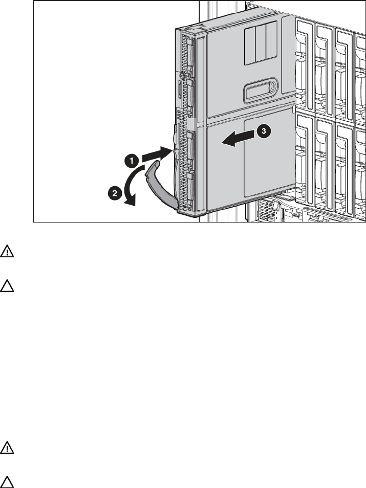
Remove the server blade
1. Identify the proper server blade.
2. Power down the server blade (on page 14).
3. Remove the server blade.
4. Place the server blade on a flat, level work surface.
WARNING: To reduce the risk of personal injury from hot surfaces, allow the drives and
the internal system components to cool before touching them.
CAUTION: To prevent damage to electrical components, properly ground the server blade before
beginning any installation procedure. Improper grounding can cause ESD.
Remove the access panel
To remove the component:
1. Power down the server blade (on page 14).
2. Remove the server blade (on page 15).
3. Lift the access panel latch and slide the access panel to the rear.
4. Remove the access panel.
WARNING: To reduce the risk of personal injury from hot surfaces, allow the drives and
the internal system components to cool before touching them.
CAUTION: To prevent damage to electrical components, properly ground the server blade before
beginning any installation procedure. Improper grounding can cause ESD.