HP ProLiant BL465c Server Blade User Guide September 2006 (First Edition) Part Number 418191-001
© Copyright 2006 Hewlett-Packard Development Company, L.P. The information contained herein is subject to change without notice. The only warranties for HP products and services are set forth in the express warranty statements accompanying such products and services. Nothing herein should be construed as constituting an additional warranty. HP shall not be liable for technical or editorial errors or omissions contained herein. Microsoft, Windows, and Windows NT are U.S.
Contents Component identification ............................................................................................................... 6 Front panel components ............................................................................................................................. 6 Front panel LEDs ....................................................................................................................................... 7 SAS and SATA hard drive LEDs.............................
Configuration tools .................................................................................................................................. 41 SmartStart software........................................................................................................................ 41 HP ROM-Based Setup Utility............................................................................................................ 41 Array Configuration Utility .................................................
POST error messages and beep codes ....................................................................................................... 64 Introduction to POST error messages ................................................................................................ 64 Processor X Unsupported Wattage................................................................................................... 65 Battery replacement ...............................................................................
Component identification In this section Front panel components ............................................................................................................................ 6 Front panel LEDs ...................................................................................................................................... 7 SAS and SATA hard drive LEDs .................................................................................................................
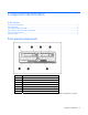
Front panel LEDs Item Description Status 1 UID LED Blue = Identified Blue flashing = Active remote management Off = No active remote management 2 Health LED Green = Normal Flashing amber = Degraded condition Flashing red = Critical condition 3 NIC 1 LED* Green = Network linked Green flashing = Network activity Off = No link or activity 4 NIC 2 LED* Green = Network linked Green flashing = Network activity Off = No link or activity 5 System power LED Green = On Amber = Standby (auxiliary pow
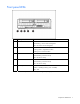
SAS and SATA hard drive LEDs Item Description 1 Fault/UID LED (amber/blue) 2 Online LED (green) SAS and SATA hard drive LED combinations Online/activity LED Fault/UID LED (green) (amber/blue) Interpretation On, off, or flashing Alternating amber and blue The drive has failed, or a predictive failure alert has been received for this drive; it also has been selected by a management application.
Online/activity LED Fault/UID LED (green) (amber/blue) Interpretation Off Steadily amber A critical fault condition has been identified for this drive, and the controller has placed it offline. Replace the drive as soon as possible. Off Amber, flashing regularly (1 Hz) A predictive failure alert has been received for this drive. Replace the drive as soon as possible. Off Off The drive is offline, a spare, or not configured as part of an array.
correspond to the symbols located on the interconnect bays. For more information, see the The symbols HP ProLiant BL465c Server Blade Installation Instructions that ship with the server blade. Mezzanine connector definitions Item PCIe Mezzanine connector 1 x4, Type I mezzanine card only Mezzanine connector 2 x8, Type 1 or II mezzanine card A PCIe x4 mezzanine connector supports x8 cards at up to x4 speeds. A PCIe x8 mezzanine connector supports x16 cards at up to x8 speeds.
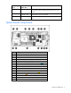
Local I/O cable Item Connector Description 1 Server blade For connecting to the local I/O cable connector on the server blade front panel 2 Video For connecting a video monitor 3 USB For connecting up to two USB devices 4 Serial For trained personnel to connect a null modem serial cable and perform advanced diagnostic procedures Component identification 11
Operations In this section Power up the server blade....................................................................................................................... 12 Power down the server blade .................................................................................................................. 12 Remove the server blade ......................................................................................................................... 13 Remove the access panel ..................
After initiating a virtual power down command, be sure that the server blade goes into standby mode by observing that the system power LED is amber. Remove the server blade To remove the component: 1. Identify the proper server blade. 2. Power down the server blade (on page 12). 3. Remove the server blade. 4. Place the server blade on a flat, level work surface.
Install the access panel 1. Place the access panel on top of the server blade with the hood latch open. Allow the panel to extend past the rear of the server blade approximately 0.8 cm (0.2 in). 2. Engage the anchoring pin with the corresponding hole in the latch. 3. Push down on the hood latch. The access panel slides to a closed position.
Setup In this section Overview .............................................................................................................................................. 15 Installing an HP BladeSystem c-Class enclosure .......................................................................................... 15 Installing server blade options.................................................................................................................. 15 Installing interconnect modules..............
Installing interconnect modules For specific steps to install interconnect modules, see the documentation that ships with the interconnect module. Interconnect bay numbering and device mapping To support network connections for specific signals, install an interconnect module in the bay corresponding to the embedded NIC or mezzanine signals.
Installing a server blade CAUTION: To prevent improper cooling and thermal damage, do not operate the server blade or the enclosure unless all hard drive and device bays are populated with either a component or a blank. 1. Remove the blank. 2. Remove the enclosure connector cover.
3. Prepare the server blade for installation. 4. Install the server blade. Completing the configuration To complete the server blade and HP BladeSystem configuration, see the overview card that ships with the enclosure.
Hardware options installation In this section Introduction ........................................................................................................................................... 19 Hard drive option................................................................................................................................... 19 Processor option.....................................................................................................................................
2. Prepare the hard drive. 3. Install the hard drive. 4. Determine the status of the hard drive from the hot-plug hard drive LEDs ("SAS and SATA hard drive LEDs" on page 8). Processor option WARNING: To reduce the risk of personal injury from hot surfaces, allow the drives and the internal system components to cool before touching them. CAUTION: To avoid damage to the system board: • Do not touch the socket contacts.
• • Handle the processor only by the edges. Do not touch the bottom of the processor, especially the contact area. CAUTION: To prevent possible server malfunction and damage to the equipment, multiprocessor configurations must contain processors with the same part number. CAUTION: The heatsink thermal interface media is not reusable and must be replaced if the heatsink is removed from the processor after it has been installed.
5. Remove the processor socket protective cover. Retain the cover for future use. CAUTION: Failure to completely open the processor retaining latch prevents the processor from seating during installation, leading to hardware damage. 6. Open the processor retaining latch and the processor socket retaining bracket. IMPORTANT: Be sure the processor remains inside the processor installation tool.
7. If the processor has separated from the installation tool, carefully re-insert the processor in the tool. 8. Align the processor installation tool with the socket and install the processor. CAUTION: The processor is designed to fit one way into the socket. Use the alignment guides on the processor and socket to properly align the processor with the socket.
9. Press down firmly until the processor installation tool clicks and separates from the processor, and then remove the processor installation tool. 10. Close the processor retaining bracket and the processor retaining latch.
11. Remove the thermal interface protective cover from the heatsink. 12. Align the tab on the processor retention bracket with the alignment slot in the heatsink. CAUTION: Heatsink retaining screws should be tightened in diagonally opposite pairs (in an "X" pattern). NOTE: The T-15 Torx screwdriver is attached to the server access panel. 13. Install the heatsink. 14. Install the access panel (on page 14). 15. Install the server blade ("Installing a server blade" on page 17).
NOTE: The Advanced Memory Protection option in RBSU provides additional memory protection beyond Advanced ECC. By default, the server is set to Advanced ECC Support. For more information, refer to "HP ROM-Based Setup Utility (on page 41)." For DIMM slot locations and bank assignments, see "DIMM slots (on page 10)." Advanced ECC memory Advanced ECC memory is the default memory protection mode for this server blade. In Advanced ECC, the server blade is protected against correctable memory errors.
4. Remove the air baffles. 5. Open the DIMM slot latches. 6. Install the DIMM. 7. Install the air baffles. 8. Install the access panel (on page 14). 9. Install the server blade ("Installing a server blade" on page 17). Mezzanine card option Optional mezzanine cards are classified as Type I mezzanine cards and Type II mezzanine cards. The card type determines where it can be installed in the server blade. • Install Type I mezzanine cards on either mezzanine 1 connector or mezzanine 2 connector.
Optional mezzanine cards enable network connectivity and provide Fibre Channel support. For mezzanine card locations, see the system board components (on page 9). For mezzanine card signal mapping, see the HP ProLiant BL465c Server Blade Installation Instructions that ship with this server blade. To install the component: 1. Power down the server blade (on page 12). 2. Remove the server blade (on page 13). 3. Remove the access panel (on page 13). 4. Remove the mezzanine connector cover. 5.
HP Smart Array E200i Battery-Backed Write Cache module option To install the component: 1. Power down the server blade (on page 12). 2. Remove the server blade (on page 13). 3. Remove the access panel (on page 13). 4. Remove the hard drives. 5. Remove the hard drive backplane. 6. Remove the front panel/hard drive cage assembly. 7. Remove the USB key, if installed.
8. Remove the Smart Array E200i cache module. 9. Install the Smart Array E200i battery pack on the new cache module provided in the option kit.
10. Install the Smart Array E200i cache module. 11. Install the USB key, if necessary. 12. Install the front panel/hard drive cage assembly. 13. Install the hard drive backplane. 14. Install the hard drives ("Hard drive option" on page 19). 15. Install the access panel (on page 14). 16. Install the server blade ("Installing a server blade" on page 17).
Cabling In this section Using the local I/O cable........................................................................................................................ 32 Connecting locally to a server blade with video and USB devices ................................................................
4. Connect a USB keyboard to the second USB connector. Item Description 1 Monitor 2 USB mouse 3 USB keyboard 4 Local I/O cable Accessing a server blade with local media devices Use the following configuration when configuring a server blade or loading software updates and patches from a USB CD/DVD-ROM or a USB diskette. 1. Connect the local I/O cable to the server blade. 2. Connect the video connector to a monitor. 3. Connect a USB hub to one USB connector. 4.
NOTE: Use a USB hub when connecting a USB diskette drive and/or USB CD-ROM drive to the server blade. The USB hub provides additional connections.
Software and configuration utilities In this section Server blade deployment tools ................................................................................................................. 35 Configuration tools ................................................................................................................................. 41 Option ROM Configuration for Arrays ...................................................................................................... 44 Management tools.
• Remotely boot a host server blade to a virtual media image to perform a ROM upgrade or install an OS. • Send alerts from iLO 2 regardless of the state of the host server blade. • Access advanced troubleshooting features provided by iLO 2. • Launch a web browser, use SNMP alerting, and diagnose the server blade with HP SIM. • Configure static IP bay settings for the dedicated iLO 2 management NICs on each server blade in an enclosure for faster deployment.
• Ethernet NIC with 10/100 RJ-45 connector • TCP/IP networking and an IP address compatible with one of the following: the iLO 2 Diagnostic Port IP address or an assigned DHCP or static IP address • CD-ROM drive, CD/DVD-ROM drive, and/or diskette drive • Any of the following Java™ Runtime Environment versions: 1.3.1_02 1.3.1_07 1.3.1_08 1.4.1 for Windows® users only 1.4.2 for Linux users only Access the Java™ Runtime Environment versions at the HP website (http://java.sun.com/products/archive/index.
Deployment methods Three primary deployment methods are supported: IMPORTANT: To deploy a server blade without the RDP, create a bootable diskette or image of a bootable diskette. • PXE deployment (on page 38) • CD-ROM deployment (on page 39) • Diskette image deployment (on page 40) PXE deployment PXE enables server blades to load an image over the network from a PXE server, and then execute it in memory.
CD-ROM deployment CD-ROM deployment involves using a bootable CD that executes scripts to configure the hardware and install the OS. After the OS is configured, the server blade can access the network to locate the scripts and files necessary for deployment. Before beginning the deployment process, connect the server blade to the network. NOTE: For more information about hardware and cabling configurations, see the documents that ship with the enclosure.
Diskette image deployment To deploy with a diskette image, the user creates a DOS-based network-enabled boot diskette that executes a script that configures the hardware and installs the OS. The diskette enables the server blade to access the required deployment scripts and files on the network. This method implies a deployment infrastructure that may include an administrator workstation, PXE server, Microsoft® Windows® file share, or a Linux file share.
Configuration tools SmartStart software SmartStart is a collection of software that optimizes single-server setup, providing a simple and consistent way to deploy server configuration. SmartStart has been tested on many ProLiant server products, resulting in proven, reliable configurations.
IMPORTANT: RBSU automatically saves settings when you press the Enter key. The utility does not prompt you for confirmation of settings before you exit the utility. To change a selected setting, you must select a different setting and press the Enter key. Auto-configuration process The auto-configuration process automatically runs when you boot the server for the first time. During the power-up sequence, the system ROM automatically configures the entire system without needing any intervention.
• Suggests the optimum configuration for an unconfigured system • Provides different operating modes, enabling faster configuration or greater control over the configuration options • Remains available any time that the server is on • Displays on-screen tips for individual steps of a configuration procedure For optimum performance, the minimum display settings are 800 × 600 resolution and 256 colors. Servers running Microsoft® operating systems require Internet Explorer 5.
10. Press the F10 key to confirm exiting RBSU. The server will automatically reboot. Option ROM Configuration for Arrays Before installing an operating system, you can use the ORCA utility to create the first logical drive, assign RAID levels, and establish online spare configurations.
• Remotely power up, power down, or reboot the host server. • Send alerts from iLO 2 regardless of the state of the host server. • Access advanced troubleshooting features through the iLO 2 interface. • Diagnose iLO 2 using HP SIM through a web browser and SNMP alerting. For more information about iLO 2 features, refer to the iLO 2 documentation on the Documentation CD or on the HP website (http://www.hp.com/servers/lights-out).
HP ProLiant Essentials Virtualization Management Software The ProLiant Essentials Virtual Machine Management Pack and ProLiant Essentials Server Migration Pack plug-ins extend HP Systems Insight Manager capabilities to manage virtual machines.
Safety and security benefits When you flash the system ROM, ROMPaq writes over the backup ROM and saves the current ROM as a backup, enabling you to switch easily to the alternate ROM version if the new ROM becomes corrupted for any reason. This feature protects the existing ROM version, even if you experience a power failure while flashing the ROM. USB support and functionality USB support HP provides both standard USB support and legacy USB support.
Survey Utility Survey Utility, a feature within HP Insight Diagnostics (on page 47), gathers critical hardware and software information on ProLiant server blades. This utility supports operating systems that may not be supported by the server blade. For operating systems supported by the server blade, refer to the HP website (http://www.hp.com/go/supportos).
For installation information, refer to the HP ISEE Client Installation and Upgrade Guide (ftp://ftp.hp.com/pub/services/hardware/info/isee_client.pdf). Web-Based Enterprise Service WEBES enables administrators to manage hardware events proactively, either locally or online. The service provides real-time multiple event analysis, crash analysis, and notification, locally through SMTP and remotely through ISEE for OpenVMS, Tru64, and Microsoft® Windows® operating system binary error logs.
Operating system version support Refer to the operating system support matrix (http://www.hp.com/go/supportos). System Online ROM flash component utility The Online ROM Flash Component Utility enables system administrators to efficiently upgrade system or controller ROM images across a wide range of servers and array controllers.
Troubleshooting In this section Troubleshooting resources ....................................................................................................................... 51 Pre-diagnostic steps ................................................................................................................................ 51 Service notifications................................................................................................................................ 54 Loose connections .......
Important safety information Familiarize yourself with the safety information in the following sections before troubleshooting the server. Important safety information Before servicing this product, read the Important Safety Information document provided with the server. Symbols on equipment The following symbols may be placed on equipment to indicate the presence of potentially hazardous conditions. This symbol indicates the presence of hazardous energy circuits or electric shock hazards.
subassembly/module-level repair. Because of the complexity of the individual boards and subassemblies, no one should attempt to make repairs at the component level or to make modifications to any printed wiring board. Improper repairs can create a safety hazard. WARNING: To reduce the risk of personal injury or damage to the equipment, be sure that: • The leveling feet are extended to the floor. • The full weight of the rack rests on the leveling feet.
NOTE: To verify the server configuration, connect to the System Management homepage and select Version Control Agent. The VCA gives you a list of names and versions of all installed HP drivers, Management Agents, and utilities, and whether they are up to date. • HP recommends you have access to the server documentation for server-specific information. • HP recommends you have access to the SmartStart CD for value-added software and drivers required during the troubleshooting process.
Start diagnosis flowchart Use the following flowchart to start the diagnostic process.
General diagnosis flowchart The General diagnosis flowchart provides a generic approach to troubleshooting. If you are unsure of the problem, or if the other flowcharts do not fix the problem, use the following flowchart. Item See 1 "Symptom information (on page 53)" 2 "Loose connections (on page 54)" 3 "Service notifications (on page 54)" 4 The most recent version of a particular server or option firmware is available on the following websites: • HP Support website (http://www.hp.
Server blade power-on problems flowchart Symptoms: • The server does not power on. • The system power LED is off or amber. • The health LED is red or amber.
NOTE: For the location of server LEDs and information on their statuses, refer to the server documentation. Possible causes: • Improperly seated or faulty power supply • Loose or faulty power cord • Power source problem • Power on circuit problem • Improperly seated component or interlock problem • Faulty internal component Item See 1 "Component identification (on page 6)" 2 Maintenance and service guides for c-Class server blades, located on the HP website (http://www.hp.
POST problems flowchart Symptoms: • Server does not complete POST NOTE: The server has completed POST when the system attempts to access the boot device.
OS boot problems flowchart There are two ways to use SmartStart when diagnosing OS boot problems on a server blade: • Use iLO to remotely attach virtual devices to mount the SmartStart CD onto the server blade. • Use a local I/O cable and drive to connect to the server blade, and then restart the server blade.
Possible causes: • Corrupted OS • Hard drive subsystem problem • Incorrect boot order setting in RBSU Item See 1 HP ROM-Based Setup Utility User Guide (http://www.hp.com/servers/smartstart) 2 "POST problems flowchart (on page 59)" 3 • "Hard drive problems" in the HP ProLiant Servers Troubleshooting Guide located on the Documentation CD or on the HP website (http://www.hp.
* See the server blade OS boot problems flowchart (on page 60) Server fault indications flowchart Symptoms: • Server boots, but a fault event is reported by Insight Management Agents (on page 45) • Server boots, but the internal health LED, external health LED, or component health LED is red or amber NOTE: For the location of server LEDs and information on their statuses, refer to the server documentation.
Possible causes: • Improperly seated or faulty internal or external component • Unsupported component installed • Redundancy failure • System overtemperature condition Item See 1 "Management agents (on page 45)" or in the HP ProLiant Servers Troubleshooting Guide located on the Documentation CD or on the HP website (http://www.hp.com/support) 2 • "Integrated Management Log" or in the HP ProLiant Servers Troubleshooting Guide located on the Documentation CD or on the HP website (http://www.hp.
POST error messages and beep codes Introduction to POST error messages The error messages and codes in this section include all new messages generated by this server blade. Some messages are informational and do not indicate an error. A server blade generates only the codes that are applicable to its configuration and options.
For a complete listing of error messages, refer to the "POST error messages" in the HP ProLiant Servers Troubleshooting Guide located on the Documentation CD or on the HP website (http://www.hp.com/support). WARNING: To avoid potential problems, ALWAYS read the warnings and cautionary information in the server documentation before removing, replacing, reseating, or modifying system components. Processor X Unsupported Wattage.
Battery replacement If the server blade no longer automatically displays the correct date and time, you may need to replace the battery that provides power to the real-time clock. Under normal use, battery life is 5 to 10 years. WARNING: The computer contains an internal lithium manganese dioxide, a vanadium pentoxide, or an alkaline battery pack. A risk of fire and burns exists if the battery pack is not properly handled. To reduce the risk of personal injury: • Do not attempt to recharge the battery.
Regulatory compliance notices In this section Regulatory compliance identification numbers ........................................................................................... 67 Federal Communications Commission notice ............................................................................................. 67 Declaration of conformity for products marked with the FCC logo, United States only..................................... 68 Modifications...................................................
Class A equipment This equipment has been tested and found to comply with the limits for a Class A digital device, pursuant to Part 15 of the FCC Rules. These limits are designed to provide reasonable protection against harmful interference when the equipment is operated in a commercial environment. This equipment generates, uses, and can radiate radio frequency energy and, if not installed and used in accordance with the instructions, may cause harmful interference to radio communications.
Modifications The FCC requires the user to be notified that any changes or modifications made to this device that are not expressly approved by Hewlett-Packard Company may void the user’s authority to operate the equipment. Cables Connections to this device must be made with shielded cables with metallic RFI/EMI connector hoods in order to maintain compliance with FCC Rules and Regulations.
Disposal of waste equipment by users in private households in the European Union This symbol on the product or on its packaging indicates that this product must not be disposed of with your other household waste. Instead, it is your responsibility to dispose of your waste equipment by handing it over to a designated collection point for the recycling of waste electrical and electronic equipment.
Korean notice Class A equipment Class B equipment Laser compliance This product may be provided with an optical storage device (that is, CD or DVD drive) and/or fiber optic transceiver. Each of these devices contains a laser that is classified as a Class 1 Laser Product in accordance with US FDA regulations and the IEC 60825-1. The product does not emit hazardous laser radiation. Each laser product complies with 21 CFR 1040.10 and 1040.11 except for deviations pursuant to Laser Notice No.
• • • Do not attempt to recharge the battery. Do not expose the battery to temperatures higher than 60°C (140°F). Do not disassemble, crush, puncture, short external contacts, or dispose of in fire or water. Batteries, battery packs, and accumulators should not be disposed of together with the general household waste. To forward them to recycling or proper disposal, please use the public collection system or return them to HP, an authorized HP Partner, or their agents.
Electrostatic discharge In this section Preventing electrostatic discharge............................................................................................................. 73 Grounding methods to prevent electrostatic discharge ................................................................................ 73 Preventing electrostatic discharge To prevent damaging the system, be aware of the precautions you need to follow when setting up the system or handling parts.
Specifications In this section Environmental specifications .................................................................................................................... 74 Server blade specifications......................................................................................................................
Technical support In this section Before you contact HP............................................................................................................................. 75 HP contact information............................................................................................................................ 75 Customer Self Repair ..............................................................................................................................
• Mandatory—Parts for which customer self repair is mandatory. If you request HP to replace these parts, you will be charged for the travel and labor costs of this service. • Optional—Parts for which customer self repair is optional. These parts are also designed for customer self repair. If, however, you require that HP replace them for you, there may or may not be additional charges, depending on the type of warranty service designated for your product.
Pour plus d'informations sur le programme CSR de HP, contactez votre Mainteneur Agrée local. Pour plus d'informations sur ce programme en Amérique du Nord, consultez le site Web HP (http://www.hp.com/go/selfrepair). Riparazione da parte del cliente Per abbreviare i tempi di riparazione e garantire una maggiore flessibilità nella sostituzione di parti difettose, i prodotti HP sono realizzati con numerosi componenti che possono essere riparati direttamente dal cliente (CSR, Customer Self Repair).
CSR-Teile werden abhängig von der Verfügbarkeit und vom Lieferziel am folgenden Geschäftstag geliefert. Für bestimmte Standorte ist eine Lieferung am selben Tag oder innerhalb von vier Stunden gegen einen Aufpreis verfügbar. Wenn Sie Hilfe benötigen, können Sie das HP technische Support Center anrufen und sich von einem Mitarbeiter per Telefon helfen lassen. Den Materialien, die mit einem CSRErsatzteil geliefert werden, können Sie entnehmen, ob das defekte Teil an HP zurückgeschickt werden muss.
Customer Self Repair Veel onderdelen in HP producten zijn door de klant zelf te repareren, waardoor de reparatieduur tot een minimum beperkt kan blijven en de flexibiliteit in het vervangen van defecte onderdelen groter is. Deze onderdelen worden CSR-onderdelen (Customer Self Repair) genoemd.
Conforme a disponibilidade e o local geográfico, as peças CSR serão enviadas no primeiro dia útil após o pedido. Onde as condições geográficas permitirem, a entrega no mesmo dia ou em quatro horas pode ser feita mediante uma taxa adicional. Se precisar de auxílio, entre em contato com o Centro de suporte técnico da HP para que um técnico o ajude por telefone. A HP especifica nos materiais fornecidos com a peça CSR de reposição se a peça com defeito deve ser devolvida à HP.
Technical support 81
Technical support 82
Acronyms and abbreviations ABEND abnormal end ACU Array Configuration Utility ADU Array Diagnostics Utility AMP Advanced Memory Protection ASR Automatic Server Recovery BBWC battery-backed write cache BIOS Basic Input/Output System CSR Customer Self Repair DHCP Dynamic Host Configuration Protocol DIMM dual inline memory module FC Fibre Channel iLO 2 Integrated Lights-Out 2 Acronyms and abbreviations 83
IML Integrated Management Log NBP Network Bootstrap Program ORCA Option ROM Configuration for Arrays PCIe peripheral component interconnect express POST Power-On Self Test PXE Preboot Execution Environment RBSU ROM-Based Setup Utility SAS serial attached SCSI SATA serial ATA SIM Systems Insight Manager UID unit identification USB universal serial bus VCA Version Control Agent VCRM Version Control Repository Manager Acronyms and abbreviations 84
Index A E access panel 13, 14 ACU (Array Configuration Utility) 42 ADU (Array Diagnostic Utility) 48 ASR (Automatic Server Recovery) 44, 83 Automatic Server Recovery (ASR) 44, 83 electrostatic discharge 73 Erase Utility 45 error messages 64 European Union notice 69 B battery 66, 71 battery replacement notice 66, 71 BBWC (battery-backed write cache) 29 beep codes 64 BIOS Serial Console 42 BIOS upgrade 44 BSMI notice 70 buttons 6 C cables 54, 69 cabling 32 cache module 29 Canadian notice 69 Care Pack 50
installation, server options 19 installing hardware 19 Integrated Management Log (IML) 48 internal USB connector 47 J Japanese notice 70 K Korean notices 71 L laser devices 71 LEDs 6 LEDs, front panel 7 LEDs, hard drive 8 local I/O cable 6, 11, 32 local I/O cable connector 6, 32 loose connections 54 M Management Agents 45 management tools 35, 44 memory 25, 26 memory, mirrored 42 mezzanine board connectors 9 mezzanine card 27 O Online ROM Flash Component Utility 50 operating systems 50 operations 12 opt
System Erase Utility 45 system maintenance switch 10 Systems Insight Manager 45 T Taiwan battery recycling notice 72 technical support 75 telephone numbers 75 troubleshooting 51 U UID LEDs 6 updating the system ROM 46 USB connectors 11 USB support 47 utilities 35 utilities, deployment 38, 41 V video connector 11 Index 87