HP ProLiant BL465c G7 Server Blade User Guide Part Number 594691-001 June 2010 (First Edition)
© Copyright 2010 Hewlett-Packard Development Company, L.P. The information contained herein is subject to change without notice. The only warranties for HP products and services are set forth in the express warranty statements accompanying such products and services. Nothing herein should be construed as constituting an additional warranty. HP shall not be liable for technical or editorial errors or omissions contained herein. Microsoft, Windows, Windows Server, and Windows NT are U.S.
Contents Component identification ............................................................................................................... 6 Front panel components ................................................................................................................................ 6 Front panel LEDs .......................................................................................................................................... 6 SAS and SATA hard drive LEDs .......................
Cache module capacitor cabling ................................................................................................................. 39 Using the HP c-Class Blade SUV Cable ......................................................................................................... 40 Connecting locally to a server blade with video and USB devices ................................................................... 40 Accessing a server blade with local KVM ...........................................
Server blade power-on problems flowchart ......................................................................................... 67 POST problems flowchart .................................................................................................................. 69 OS boot problems flowchart .............................................................................................................. 71 Server fault indications flowchart ............................................................
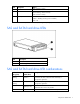
Component identification Front panel components Item Description 1 Serial label pull tab 2 SUV connector* 3 Server blade release button 4 Power On/Standby button 5 Server blade release lever 6 Hard drive bays * The SUV connector and the HP c-Class Blade SUV cable are for some server blade configuration and diagnostic procedures.
Item Description Status Off = No link or activity 4 Flex 2 LED* Green = Network linked Green flashing = Network activity Off = No link or activity 5 System power LED Green = On Amber = Standby (auxiliary power available) Off = Off * Actual NIC numbers depend on several factors, including the operating system installed on the server blade.
Online/activity LED (green) Fault/UID LED (amber/blue) Interpretation Flashing regularly (1 Hz) Amber, flashing regularly (1 Hz) Do not remove the drive. Removing a drive may terminate the current operation and cause data loss. The drive is part of an array that is undergoing capacity expansion or stripe migration, but a predictive failure alert has been received for this drive. To minimize the risk of data loss, do not replace the drive until the expansion or migration is complete.
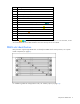
Item Description 1 DIMM slots (Processor 2) 2 DIMM slots (Processor 1) 3 Smart Array connector 4 TPM security rivet (optional) 5 Micro SD connnector 6 Internal USB connector 7 Mezzanine connector 2 (Type I or Type II mezzanine) 8 Enclosure connector 9 Mezzanine connector 1 (Type I mezzanine only) 10 System maintenance switch (SW1) 11 Embedded NICs (2) 12 Battery 13 Processor socket 1 (populated) 14 Processor socket 2 The symbols correspond to the symbols located on the intercon
Mezzanine connector definitions Item PCIe Mezzanine connector 1 x8, Type I mezzanine card only Mezzanine connector 2 x8, Type I or II mezzanine card System maintenance switch Position Function Default 1* iLO 3 security override Off 2 Configuration lock Off 3 Reserved Off 4 Reserved Off 5* Password disabled Off 6* Reset configuration Off 7 Reserved Off 8 Reserved Off 9 Reserved Off 10 Reserved Off *To access redundant ROM, set S1, S5, and S6 to ON.
8. Repeat steps 1 through 3. 9. Change position 6 of the system maintenance switch to off. 10. Repeat steps 5 and 6. IMPORTANT: When the server blade boots after NVRAM is cleared, a delay of up to 2 minutes is normal. During this delay, the system appears non-functional. Do not attempt any procedures during the delay. Accessing the redundant ROM If the system ROM is corrupted, the system automatically switches to the redundant ROM in most cases.
Item Connector Description 1 Server blade For connecting to the SUV connector on the server blade front panel 2 Video For connecting a video monitor 3 USB For connecting up to two USB devices 4 Serial For trained personnel to connect a null modem serial cable and perform advanced diagnostic procedures Component identification 12
Operations Power up the server blade The Onboard Administrator initiates an automatic power-up sequence when the server blade is installed. If the default setting is changed, use one of the following methods to power up the server blade: • Use a virtual power button selection through iLO 3. • Press and release the Power On/Standby button. When the server blade goes from the standby mode to the full power mode, the system power LED changes from amber to green.
a. Select the Enclosure Information tab, then select the Overall checkbox in the Device Bays item. b. Initiate a shutdown from the Virtual Power menu: — Select Momentary Press to initiate a controlled shutdown of applications and the OS. — Select Press and Hold to initiate an emergency shutdown of applications and the OS. IMPORTANT: When the server blade are in standby mode, auxiliary power is still being provided. To remove all power from the server blade, remove the server blade from the enclosure.
Remove the access panel To remove the component: 1. Power down the server blade (on page 13). 2. Remove the server blade (on page 14). 3. Lift the access panel latch and slide the access panel to the rear. 4. Remove the access panel. WARNING: To reduce the risk of personal injury from hot surfaces, allow the drives and the internal system components to cool before touching them.
Setup Overview Installation of a server blade requires the following steps: 1. Install and configure an HP BladeSystem c-Class enclosure. 2. Install any server blade options. 3. Install interconnect modules in the enclosure. 4. Connect the interconnect modules to the network. 5. Install a server blade. 6. Complete the server blade configuration.
To support network connections for specific signals, install an interconnect module in the bay corresponding to the embedded NIC or mezzanine signals. Server blade signal Interconnect bay NIC 1 (Embedded) 1 NIC 2 (Embedded) 2 Mezzanine 1 3 and 4 Mezzanine 2 5 and 6 Interconnect bay labels 7 and 8 For detailed port mapping information, see the HP BladeSystem enclosure installation poster or the HP BladeSystem enclosure setup and installation guide on the HP website (http://www.hp.
Server blade signal Interconnect bay number NICs 1, 2 (embedded) 1 — Mezzanine 1 2 Four port cards connect to bay 2 Mezzanine 2 3,4 • • • Interconnect bay label Notes Four port cards Ports 1 and 3 connect to bay 3 Ports 2 and 4 connect to bay 4 Connecting to the network To connect the HP BladeSystem to a network, each enclosure must be configured with network interconnect devices to manage signals between the server blades and the external network.
2. 3. Remove the enclosure connector cover. Prepare the server blade for installation.
4. Install the server blade. Completing the configuration To complete the server blade and HP BladeSystem configuration, see the overview card that ships with the enclosure.
Hardware options installation Introduction If more than one option is being installed, read the installation instructions for all the hardware options and identify similar steps to streamline the installation process. WARNING: To reduce the risk of personal injury from hot surfaces, allow the drives and the internal system components to cool before touching them. CAUTION: To prevent damage to electrical components, properly ground the server before beginning any installation procedure.
Memory subsystem architecture The memory subsystem in this server blade is divided into channels. Each processor supports four channels, and each channel supports two DIMM slots, as shown in the following table. Channel Slot Slot number 1 A E 1 2 2 C G 3 4 3 B F 5 6 4 D H 7 8 This multi-channel architecture provides enhanced performance in Advanced ECC mode. This server blade supports both Registered PC3 DIMMs (RDIMMs) and Unbuffered DIMMs (UDIMMs).
Item Description Definition 4 Voltage rating L = Low voltage (1.35v) Blank or omitted = Standard 5 Memory speed 10600 = 1333-MHz 8500 = 1066-MHz 6 DIMM type R = RDIMM (registered) E = UDIMM (unbuffered with ECC) For the latest supported memory information, see the QuickSpecs on the HP website (http://www.hp.com). Advanced ECC memory configuration Advanced ECC memory is the default memory protection mode for this server blade.
IMPORTANT: This server blade does not support mixing RDIMMs and UDIMMs. Attempting to mix these two types causes the server to halt during BIOS initialization.
6. Install the DIMM. 7. Install the DIMM baffle. 8. Connect the hard drive cables ("Hot-plug SAS/SATA hard drive cabling" on page 39). 9. Connect the cache module capacitor cable ("Cache module capacitor cabling" on page 39). 10. Install the access panel (on page 15). 11. Install the server blade ("Installing a server blade" on page 18). Hot-plug SAS or SATA hard drive option IMPORTANT: To avoid improper operation, install only hot-plug hard drives in this server blade.
To install the component: 1. Remove the hard drive blank. 2. Release the hard drive tray, slide it forward until it locks, and then press hard drive carrier 1 down to access hard drive carrier 2. 3. Prepare the hard drive. 4. Install hard drive 2, and then lift hard drive carrier 1 into position in the hard drive tray.
5. Slide the hard drive tray into the server blade until it locks. 6. Prepare the hard drive. 7. Install hard drive 1. 8. Determine the status of the hard drive from the hot-plug hard drive LEDs ("SAS and SATA hard drive LEDs" on page 7).
Mezzanine card option Optional mezzanine cards provide additional network connectivity or provide Fibre Channel support. For mezzanine card locations, see "System board components (on page 8)." For mezzanine card signal mapping, see "Interconnect bay numbering and device mapping (on page 16)" and the installation instructions that ship with the server blade. Optional mezzanine cards are classified as Type I mezzanine cards and Type II mezzanine cards.
CAUTION: To prevent damage to the server blade, apply pressure over the mezzanine connector when installing the mezzanine card. Do not apply pressure to the edges of the card. 6. Install the mezzanine card. Press down on the connector to seat the card. 7. Install the access panel (on page 15). 8. Install the server blade ("Installing a server blade" on page 18). 9. Power up the server blade (on page 13).
To install a processor: 1. Locate and download the latest ROM version from the HP website (http://www.hp.com/support). Follow the instructions on the website to update the system ROM. 2. Power down the server blade (on page 13). 3. Remove the server blade (on page 14). 4. If installed, remove the hard drives: a. Remove hard drive 1. b. Release the hard drive tray, slide it forward until it locks, and then press hard drive carrier 1 down to access hard drive 2.
c. Remove hard drive 2. d. Lift hard drive carrier 1 into position in the hard drive tray, and then slide the hard drive tray into the server blade until it locks. 5. Remove the access panel (on page 15). 6. Disconnect the SAS/SATA cables and power cable from the hard drive backplane, and then remove the front bezel/hard drive cage assembly.
7. Remove the heatsink blank. Retain the heatsink blank for future use. CAUTION: Failure to completely open the processor retaining latch prevents the processor from seating during installation, leading to hardware damage. 8. Open the processor retaining latch and the processor socket retaining bracket. CAUTION: The pins on the processor socket are very fragile. Any damage to them may require replacing the system board.
9. Remove the processor socket protective cover. Retain the cover for future use. IMPORTANT: Be sure the processor remains inside the processor installation tool. 10. If the processor has separated from the installation tool, carefully re-insert the processor into the tool. 11. Align the processor installation tool with the socket and install the processor. CAUTION: The processor is designed to fit one way into the socket.
12. Press in firmly until the processor installation tool clicks and separates from the processor, and then remove the processor installation tool.
13. Close the processor retaining bracket and the processor retaining latch. CAUTION: To avoid damage to the system board, processor socket, and screws, do not overtighten the heatsink screws. Use the wrench supplied with the system to reduce the possibility of overtightening the screws. 14. Align and install the heatsink. Alternate tightening the screws until the heatsink is seated properly. 15. Install the front bezel/hard drive cage assembly. 16.
HP Trusted Platform Module option Use these instructions to install and enable a TPM on a supported server blade. This procedure includes three sections: 1. Installing the Trusted Platform Module board. 2. Retaining the recovery key/password (on page 37). 3. Enabling the Trusted Platform Module (on page 38). Enabling the TPM requires accessing the ROM-Based Setup Utility (RBSU) ("HP ROM-Based Setup Utility" on page 50). For more information about RBSU, see the HP website (http://www.hp.
CAUTION: Any attempt to remove an installed TPM from the system board breaks or disfigures the TPM security rivet. Upon locating a broken or disfigured rivet on an installed TPM, administrators should consider the system compromised and take appropriate measures to ensure the integrity of the system data. 5. Install the TPM board. Press down on the connector to seat the board ("System board components" on page 8). 6. Install the TPM security rivet by pressing the rivet firmly into the system board. 7.
To help ensure maximum security, observe the following guidelines when retaining the recovery key/password: • Always store the recovery key/password in multiple locations. • Always store copies of the recovery key/password away from the server blade. • Do not save the recovery key/password on the encrypted hard drive. Enabling the Trusted Platform Module 1. When prompted during the start-up sequence, access RBSU by pressing the F9 key. 2. From the Main Menu, select Server Security. 3.
Cabling Hot-plug SAS/SATA hard drive cabling Cache module capacitor cabling Cabling 39
Using the HP c-Class Blade SUV Cable The HP c-Class Blade SUV Cable enables the user to perform server blade administration, configuration, and diagnostic procedures by connecting video and USB devices directly to the server blade. For SUV cable connectors, see "HP c-Class Blade SUV Cable (on page 11).
4. Connect a USB keyboard to the second USB connector. Item Description 1 Monitor 2 USB mouse 3 USB keyboard 4 HP c-Class Blade SUV Cable Accessing a server blade with local media devices Use the following configuration when configuring a server blade or loading software updates and patches from a USB CD/DVD-ROM or a USB diskette. 1. Connect the local I/O cable to the server blade. 2. Connect the video connector to a monitor. 3. Connect a USB hub to one USB connector. 4.
Item Description 1 Monitor 2 USB CD/DVD-ROM drive or diskette drive 3 USB keyboard 4 USB hub 5 USB mouse 6 Local I/O cable Cabling 42
Software and configuration utilities Server blade deployment tools Software drivers and additional components HP offers the following additional software components for server blades: • Health and Wellness driver and IML viewer • iLO 3 Management interface driver • Rack infrastructure interface service For Microsoft® Windows® OS users, these items are included in the HP ProLiant iLO 3 Standard Blade Edition, available from the HP website (http://www.hp.com/servers/lights-out).
To connect to the server blade using iLO 3, install the server blade in an enclosure. Onboard Administrator assigns an IP address to enable iLO 3 connectivity to the server blade. The c-Class tab enables you to control specific settings for the HP BladeSystem. iLO 3 also provides webbased status for the HP BladeSystem configuration. For detailed information about iLO 3, refer to the HP Integrated Lights-Out User Guide on the HP website (http://www.hp.com/servers/lights-out).
o TCP/IP networking and an IP address compatible with one of the following: the iLO 3 Diagnostic Port IP address or an assigned DHCP or static IP address o CD-ROM drive, CD/DVD-ROM drive, and/or diskette drive o Any of the following Java™ Runtime Environment versions: 1.3.1_02 1.3.1_07 1.3.1_08 1.4.1 for Windows® users only 1.4.2 for Linux users only Access the Java™ Runtime Environment versions at the HP website (http://java.sun.com/products/archive/index.html).
Deployment methods Three primary deployment methods are supported: IMPORTANT: To deploy a server blade without the RDP, create a bootable diskette or image of a bootable diskette. • PXE deployment (on page 46) • CD-ROM deployment (on page 47) • Diskette image deployment (on page 48) PXE deployment PXE enables server blades to load an image over the network from a PXE server, and then execute it in memory.
Using SmartStart technology, the Scripting Toolkit provides a flexible way to create standard server configuration scripts. These scripts are used to automate many of the manual steps in the server configuration process. This automated server configuration process cuts time from each deployment, making it possible to scale server deployments to high volumes in a rapid manner. For more information, and to download the SmartStart Scripting Toolkit, see the HP website (http://www.hp.com/servers/sstoolkit).
4. After the server blade boots, follow the normal installation procedure for an OS. Windows Server® 2003 cannot be installed from a USB CD-ROM on the I/O cable if the hard drive is completely blank (no partitions defined). To install Windows Server® 2003, use one of the following methods: • Make a partition on the hard drive that Windows Server® 2003 will be loaded on. • Use the SmartStart CD 7.60 or later. • Use the Rapid Deployment Pack. For instructions, see the HP website (http://h18013.www1.
Creating a boot diskette The SmartStart Scripting Toolkit provides the tools and information for creating a boot diskette. For details, refer to the SmartStart Scripting Toolkit User Guide and download the latest version of the software from the HP website (http://www.hp.com/servers/sstoolkit). As an alternative method, configure the hardware manually with RBSU and the iLO 3 remote console. With this method, the disk is more generic and integrates with an existing network OS installation process.
HP ROM-Based Setup Utility RBSU is a configuration utility embedded in ProLiant servers that performs a wide range of configuration activities that can include the following: • Configuring system devices and installed options • Enabling and disabling system features • Displaying system information • Selecting the primary boot controller • Configuring memory options • Language selection For more information on RBSU, see the HP ROM-Based Setup Utility User Guide on the Documentation CD or the HP
Drives installed Drives used RAID level 1 1 RAID 0 2 2 RAID 1 3, 4, 5, or 6 3, 4, 5, or 6 RAID 5 More than 6 0 None To change any ORCA default settings and override the auto-configuration process, press the F8 key when prompted. For more information on RBSU, see the HP ROM-Based Setup Utility User Guide on the Documentation CD or the HP website (http://www.hp.com/support/smartstart/documentation). Boot options Near the end of the boot process, the boot options screen is displayed.
mirrored copy. The system continues to operate normally without any user intervention. If the system supports hot-plug memory, the failed memory can be replaced while the system continues to operate. • RAID Memory Mode—Provides protection levels similar to Mirrored Memory Mode, and it requires less memory allocation than full redundancy.
Re-entering the server serial number and product ID After you replace the system board, you must re-enter the server blade serial number and the product ID. 1. During the server blade startup sequence, press the F9 key to access RBSU. 2. Select the Advanced Options menu. 3. Select Service Options. 4. Select Serial Number. The following warnings appear: WARNING! WARNING! WARNING! The serial number is loaded into the system during the manufacturing process and should NOT be modified.
The ROMPaq utility checks the system and provides a choice (if more than one exists) of available firmware revisions. For more information, see the Download drivers and software page for the server blade. To access the server-specific page, enter the following web address into the browser: http://www.hp.com/support/ For example: http://www.hp.
HP Systems Insight Manager HP SIM is a web-based application that allows system administrators to accomplish normal administrative tasks from any remote location, using a web browser. HP SIM provides device management capabilities that consolidate and integrate management data from HP and third-party devices. IMPORTANT: You must install and use HP SIM to benefit from the Pre-Failure Warranty for processors, SAS and SATA hard drives, and memory modules.
Internal USB functionality An internal USB connector is available for use with security key devices and USB drive keys. This solution provides for use of a permanent USB key installed in the internal connector, avoiding issues of clearance on the front of the rack and physical access to secure data. External USB functionality HP provides external USB support to enable local connection of USB devices for server blade administration, configuration, and diagnostic procedures.
NOTE: The current version of SmartStart provides the memory spare part numbers for the server blade. To download the latest version, see the HP website (http://www.hp.com/support). Integrated Management Log The IML records hundreds of events and stores them in an easy-to-view form. The IML timestamps each event with 1-minute granularity.
proactive service support for nearly all HP servers, storage, network and SAN environments, plus selected Dell and IBM Windows servers that have a support obligation with HP. It also enables HP to deliver higher levels of proactive support in line with HP Mission Critical Services support agreements. Download from the HP website (http://h20392.www2.hp.com/portal/swdepot/displayProductInfo.do?productNumber=ISDVD).
For more information about version control tools, see the HP Systems Insight Manager Help Guide and the Version Control User Guide on the HP Systems Insight Manager website (http://www.hp.com/go/hpsim). ProLiant Support Packs PSPs represent operating system-specific bundles of ProLiant optimized drivers, utilities, and management agents. Refer to the PSP website (http://h18000.www1.hp.com/products/servers/management/psp.html).
• Deploys necessary component updates only (except Linux RPMs) • Downloads the latest components from Web (except Linux RPMs) • Enables direct update of BMC firmware (iLO and LO100i) For more information about HP Smart Update Manager and to access the HP Smart Update Manager User Guide, see the HP website (http://www.hp.com/go/foundation).
Troubleshooting Troubleshooting resources The HP ProLiant Servers Troubleshooting Guide provides procedures for resolving common problems and comprehensive courses of action for fault isolation and identification, error message interpretation, issue resolution, and software maintenance on ProLiant servers and server blades. This guide includes problemspecific flowcharts to help you navigate complex troubleshooting processes. To view the guide, select a language: • English (http://www.hp.
Important safety information Before servicing this product, read the Important Safety Information document provided with the server. Symbols on equipment The following symbols may be placed on equipment to indicate the presence of potentially hazardous conditions. This symbol indicates the presence of hazardous energy circuits or electric shock hazards. Refer all servicing to qualified personnel. WARNING: To reduce the risk of injury from electric shock hazards, do not open this enclosure.
WARNING: To reduce the risk of personal injury or damage to the equipment, be sure that: • The leveling feet are extended to the floor. • The full weight of the rack rests on the leveling feet. • The stabilizing feet are attached to the rack if it is a single-rack installation. • The racks are coupled together in multiple-rack installations. • Only one component is extended at a time. A rack may become unstable if more than one component is extended for any reason.
o HP recommends you have access to the server documentation for server-specific information. o HP recommends you have access to the SmartStart CD for value-added software and drivers required during the troubleshooting process. Download the current version of SmartStart from the HP website (http://www.hp.com/servers/smartstart). Service notifications To view the latest service notifications, refer to the HP website (http://www.hp.com/go/bizsupport).
Start diagnosis flowchart Use the following flowchart to start the diagnostic process.
General diagnosis flowchart The General diagnosis flowchart provides a generic approach to troubleshooting. If you are unsure of the problem, or if the other flowcharts do not fix the problem, use the following flowchart. Item See 1 "Symptom information (on page 63)" 2 "Loose connections (on page 64)" 3 "Service notifications (on page 64)" 4 The most recent version of a particular server blade or option firmware is available on the HP Support website (http://www.hp.com/support).
Server blade power-on problems flowchart Symptoms: • The server does not power on. • The system power LED is off or amber.
• The health LED is red or amber. NOTE: For the location of server LEDs and information on their statuses, refer to the server documentation.
POST problems flowchart Symptoms: • Server does not complete POST NOTE: The server has completed POST when the system attempts to access the boot device.
Item Refer to 1 Server blade power-on problems flowchart (on page 67) 2 "POST error messages and beep codes (on page 75)" 3 "Video problems" in the HP ProLiant Servers Troubleshooting Guide located on the Documentation CD or on the HP website (http://www.hp.com/support) 4 "Symptom information (on page 63)" 5 "General memory problems are occurring" in the HP ProLiant Servers Troubleshooting Guide located on the Documentation CD or on the HP website (http://www.hp.
OS boot problems flowchart There are two ways to use SmartStart when diagnosing OS boot problems on a server blade: • Use iLO to remotely attach virtual devices to mount the SmartStart CD onto the server blade. • Use a local I/O cable and drive to connect to the server blade, and then restart the server blade.
Possible causes: • Corrupted OS • Hard drive subsystem problem • Incorrect boot order setting in RBSU Item See 1 HP ROM-Based Setup Utility User Guide (http://www.hp.com/servers/smartstart) 2 "POST problems flowchart (on page 69)" 3 • "Hard drive problems" in the HP ProLiant Servers Troubleshooting Guide located on the Documentation CD or on the HP website (http://www.hp.
* See the server blade OS boot problems flowchart (on page 71) Server fault indications flowchart Symptoms: • Server boots, but a fault event is reported by Insight Management Agents • Server boots, but the internal health LED, external health LED, or component health LED is red or amber Troubleshooting 73
NOTE: For the location of server LEDs and information on their statuses, refer to the server documentation. Possible causes: • Improperly seated or faulty internal or external component • Unsupported component installed • Redundancy failure • System overtemperature condition Item See 1 "Management agents" or in the HP ProLiant Servers Troubleshooting Guide located on the Documentation CD or on the HP website (http://www.hp.
POST error messages and beep codes Introduction to POST error messages The error messages and codes in this section include all new messages generated by this server blade. Some messages are informational and do not indicate an error. A server blade generates only the codes that are applicable to its configuration and options.
For a complete listing of error messages, refer to the "POST error messages" in the HP ProLiant Servers Troubleshooting Guide located on the Documentation CD or on the HP website (http://www.hp.com/support). WARNING: To avoid potential problems, ALWAYS read the warnings and cautionary information in the server documentation before removing, replacing, reseating, or modifying system components. Processor X Unsupported Wattage.
Battery replacement If the server blade no longer automatically displays the correct date and time, you may need to replace the battery that provides power to the real-time clock. Under normal use, battery life is 5 to 10 years. WARNING: The computer contains an internal lithium manganese dioxide, a vanadium pentoxide, or an alkaline battery pack. A risk of fire and burns exists if the battery pack is not properly handled. To reduce the risk of personal injury: • Do not attempt to recharge the battery.
Regulatory compliance notices Regulatory compliance identification numbers For the purpose of regulatory compliance certifications and identification, this product has been assigned a unique regulatory model number. The regulatory model number can be found on the product nameplate label, along with all required approval markings and information. When requesting compliance information for this product, always refer to this regulatory model number.
to radio communications. However, there is no guarantee that interference will not occur in a particular installation. If this equipment does cause harmful interference to radio or television reception, which can be determined by turning the equipment off and on, the user is encouraged to try to correct the interference by one or more of the following measures: • Reorient or relocate the receiving antenna. • Increase the separation between the equipment and receiver.
Canadian notice (Avis Canadien) Class A equipment This Class A digital apparatus meets all requirements of the Canadian Interference-Causing Equipment Regulations. Cet appareil numérique de la classe A respecte toutes les exigences du Règlement sur le matériel brouilleur du Canada. Class B equipment This Class B digital apparatus meets all requirements of the Canadian Interference-Causing Equipment Regulations.
Disposal of waste equipment by users in private households in the European Union This symbol on the product or on its packaging indicates that this product must not be disposed of with your other household waste. Instead, it is your responsibility to dispose of your waste equipment by handing it over to a designated collection point for the recycling of waste electrical and electronic equipment.
Korean notice Class A equipment Class B equipment Chinese notice Class A equipment Laser compliance This product may be provided with an optical storage device (that is, CD or DVD drive) and/or fiber optic transceiver. Each of these devices contains a laser that is classified as a Class 1 Laser Product in accordance with US FDA regulations and the IEC 60825-1. The product does not emit hazardous laser radiation. Each laser product complies with 21 CFR 1040.10 and 1040.
WARNING: The computer contains an internal lithium manganese dioxide, a vanadium pentoxide, or an alkaline battery pack. A risk of fire and burns exists if the battery pack is not properly handled. To reduce the risk of personal injury: • Do not attempt to recharge the battery. • Do not expose the battery to temperatures higher than 60°C (140°F). • Do not disassemble, crush, puncture, short external contacts, or dispose of in fire or water.
Electrostatic discharge Preventing electrostatic discharge To prevent damaging the system, be aware of the precautions you need to follow when setting up the system or handling parts. A discharge of static electricity from a finger or other conductor may damage system boards or other static-sensitive devices. This type of damage may reduce the life expectancy of the device. To prevent electrostatic damage: • Avoid hand contact by transporting and storing products in static-safe containers.
Specifications Environmental specifications Specification Value — Temperature range* Operating 10°C to 35°C (50°F to 95°F) Non-operating -30°C to 60°C (-22°F to 140°F) Relative humidity (noncondensing)** — Operating 10% to 90% @ 28°C (82.4°F) Non-operating 5% to 95% @ 38.7°C (101.7°F) Altitude† — Operating 3050 m (10,000 ft) Non-operating 9144 m (30,000 ft) * The following temperature conditions and limitations apply: - All temperature ratings shown are for sea level.
Technical support Before you contact HP Be sure to have the following information available before you call HP: • Technical support registration number (if applicable) • Product serial number • Product model name and number • Product identification number • Applicable error messages • Add-on boards or hardware • Third-party hardware or software • Operating system type and revision level HP contact information For the name of the nearest HP authorized reseller: • See the Contact HP worldwi
• Optional—Parts for which customer self repair is optional. These parts are also designed for customer self repair. If, however, you require that HP replace them for you, there may or may not be additional charges, depending on the type of warranty service designated for your product. NOTE: Some HP parts are not designed for customer self repair. In order to satisfy the customer warranty, HP requires that an authorized service provider replace the part.
Pour plus d'informations sur le programme CSR de HP, contactez votre Mainteneur Agrée local. Pour plus d'informations sur ce programme en Amérique du Nord, consultez le site Web HP (http://www.hp.com/go/selfrepair). Riparazione da parte del cliente Per abbreviare i tempi di riparazione e garantire una maggiore flessibilità nella sostituzione di parti difettose, i prodotti HP sono realizzati con numerosi componenti che possono essere riparati direttamente dal cliente (CSR, Customer Self Repair).
HINWEIS: Einige Teile sind nicht für Customer Self Repair ausgelegt. Um den Garantieanspruch des Kunden zu erfüllen, muss das Teil von einem HP Servicepartner ersetzt werden. Im illustrierten Teilekatalog sind diese Teile mit „No“ bzw. „Nein“ gekennzeichnet. CSR-Teile werden abhängig von der Verfügbarkeit und vom Lieferziel am folgenden Geschäftstag geliefert. Für bestimmte Standorte ist eine Lieferung am selben Tag oder innerhalb von vier Stunden gegen einen Aufpreis verfügbar.
el caso de todas sustituciones que lleve a cabo el cliente, HP se hará cargo de todos los gastos de envío y devolución de componentes y escogerá la empresa de transporte que se utilice para dicho servicio. Para obtener más información acerca del programa de Reparaciones del propio cliente de HP, póngase en contacto con su proveedor de servicios local. Si está interesado en el programa para Norteamérica, visite la página web de HP siguiente (http://www.hp.com/go/selfrepair).
Opcional – Peças cujo reparo feito pelo cliente é opcional. Essas peças também são projetadas para o reparo feito pelo cliente. No entanto, se desejar que a HP as substitua, pode haver ou não a cobrança de taxa adicional, dependendo do tipo de serviço de garantia destinado ao produto. OBSERVAÇÃO: Algumas peças da HP não são projetadas para o reparo feito pelo cliente. A fim de cumprir a garantia do cliente, a HP exige que um técnico autorizado substitua a peça.
Technical support 92
Technical support 93
Acronyms and abbreviations ACU Array Configuration Utility AMP Advanced Memory Protection ASR Automatic Server Recovery BMC baseboard management controller CSR Customer Self Repair ESD electrostatic discharge IEC International Electrotechnical Commission iLO 3 Integrated Lights-Out 3 IML Integrated Management Log ORCA Option ROM Configuration for Arrays POST Power-On Self Test PSP ProLiant Support Pack Acronyms and abbreviations 94
PXE Preboot Execution Environment RBSU ROM-Based Setup Utility RPM Red Hat Package Manager SAS serial attached SCSI SATA serial ATA SD Secure Digital SIM Systems Insight Manager TPM trusted platform module UID unit identification USB universal serial bus VCA Version Control Agent Acronyms and abbreviations 95
Index A access panel 15 accessing a server blade with local KVM 40, 41 ACU (Array Configuration Utility) 52 Advanced ECC memory 23, 51 ASR (Automatic Server Recovery) 53 auto-configuration process 50 B deployment methods 43, 44, 46 diagnostic tools 53, 56 diagnostics utility 56 DIMM identification 22 DIMM installation guidelines 23 DIMM population guidelines 23 DIMM slot locations 9 DIMMs 21 disposal, battery 80, 82 drivers 43, 58 batteries, replacing 77, 82 battery 77, 82 battery disposal 80, 82 battery
HP HP HP HP HP HP Insight Diagnostics 56 Insight Remote Support software 57 ProLiant Essentials Foundation Pack 55 Smart Update Manager overview 59 Systems Insight Manager overview 55 technical support 86 I identification number 78 iLO 3 (Integrated Lights-Out 3) 54 IML (Integrated Management Log) 57 Important Safety Information document 61 Insight Diagnostics 56, 58 installation, server blade 18 installation, server options 21 installing the access panel 15 installing the Trusted Platform Module board 36
scripted installation 46 serial connector 11 serial number 53 series number 78 server fault indications flowchart 73 server features and options 21 servers, setup and configuration 16 service notifications 64 SmartStart autorun menu 49 SmartStart Scripting Toolkit 46 SmartStart, overview 49 specifications 85 start diagnosis flowchart 65 static electricity 84 support 57, 86 support packs 49 supported operating systems 59 SUV cable 11 switches, interconnect 16 symbols on equipment 62 symptom information 63 sy