HP ProLiant BL465c G6 Server Blade User Guide Part Number 574424-001 June 2009 (First Edition)
© Copyright 2009 Hewlett-Packard Development Company, L.P. The information contained herein is subject to change without notice. The only warranties for HP products and services are set forth in the express warranty statements accompanying such products and services. Nothing herein should be construed as constituting an additional warranty. HP shall not be liable for technical or editorial errors or omissions contained herein. Microsoft, Windows, Windows Server, and Windows NT are U.S.
Contents Component identification ............................................................................................................... 6 Front panel components ............................................................................................................................. 6 Front panel LEDs ....................................................................................................................................... 7 SAS and SATA hard drive LEDs.............................
Software drivers and additional components ..................................................................................... 37 HP BladeSystem c-Class Advanced management ............................................................................... 37 Network-based PXE deployment ...................................................................................................... 38 Deployment methods.....................................................................................................
Server fault indications flowchart ..................................................................................................... 68 POST error messages and beep codes ....................................................................................................... 70 Introduction to POST error messages ................................................................................................ 70 Processor X Unsupported Wattage...............................................................
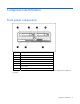
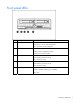
Component identification Front panel components Item Description 1 Hard drive bay 1 2 Power On/Standby button 3 SUV connector* 4 Hard drive bay 2 5 Server blade handle 6 Release button 7 Serial label pull tab * The SUV connector and the HP c-Class Blade SUV cable are for some server blade configuration and diagnostic procedures.
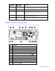
Front panel LEDs Item Description Status 1 UID LED Blue = Identified Blue flashing = Active remote management Off = No active remote management 2 Health LED Green = Normal Flashing amber = Degraded condition Flashing red = Critical condition 3 NIC 1 LED* Green = Network linked Green flashing = Network activity Off = No link or activity 4 NIC 2 LED* Green = Network linked Green flashing = Network activity Off = No link or activity 5 System power LED Green = On Amber = Standby (auxiliary pow
SAS and SATA hard drive LEDs Item Description 1 Fault/UID LED (amber/blue) 2 Online LED (green) SAS and SATA hard drive LED combinations Online/activity LED (green) Fault/UID LED (amber/blue) Interpretation On, off, or flashing Alternating amber and blue The drive has failed, or a predictive failure alert has been received for this drive; it also has been selected by a management application.
Online/activity LED (green) Fault/UID LED (amber/blue) Interpretation Flashing irregularly Amber, flashing regularly (1 Hz) The drive is active, but a predictive failure alert has been received for this drive. Replace the drive as soon as possible. Flashing irregularly Off The drive is active, and it is operating normally. Off Steadily amber A critical fault condition has been identified for this drive, and the controller has placed it offline. Replace the drive as soon as possible.
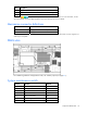
Item Description 13 DIMM slots (Processor 2 memory banks C and D) 14 HP Smart Array E200i cache module (under hard drive cage) 15 System board thumbscrew The symbols correspond to the symbols located on the interconnect bays. For more information, see the HP ProLiant BL465c G6 Server Blade Installation Instructions that ship with the server blade.
Position Function Default 8 Reserved Off *To access redundant ROM, set S1, S5, and S6 to ON.
Operations Power up the server blade The Onboard Administrator initiates an automatic power-up sequence when the server blade is installed. If the default setting is changed, use one of the following methods to power up the server blade: • Use a virtual power button selection through iLO 2. • Press and release the Power On/Standby button. When the server blade goes from the standby mode to the full power mode, the system power LED changes from amber to green.
• Use the Onboard Administrator GUI to initiate a shutdown: a. Select the Enclosure Information tab, then select the Overall checkbox in the Device Bays item. b. Initiate a shutdown from the Virtual Power menu: — Select Momentary Press to initiate a controlled shutdown of applications and the OS. — Select Press and Hold to initiate an emergency shutdown of applications and the OS. IMPORTANT: When the server blade are in standby mode, auxiliary power is still being provided.
Remove the access panel To remove the component: 1. Power down the server blade (on page 12). 2. Remove the server blade (on page 13). 3. Lift the access panel latch and slide the access panel to the rear. 4. Remove the access panel. WARNING: To reduce the risk of personal injury from hot surfaces, allow the drives and the internal system components to cool before touching them.
Setup Overview Installation of a server blade requires the following steps: 1. Install and configure an HP BladeSystem c-Class enclosure. 2. Install any server blade options. 3. Install interconnect modules in the enclosure. 4. Connect the interconnect modules to the network. 5. Install a server blade. 6. Complete the server blade configuration. Installing an HP BladeSystem c-Class enclosure Before performing any server blade-specific procedures, install an HP BladeSystem c-Class enclosure.
Interconnect bay numbering and device mapping • HP BladeSystem c7000 Enclosure To support network connections for specific signals, install an interconnect module in the bay corresponding to the embedded NIC or mezzanine signals.
• HP BladeSystem c3000 Enclosure and Tower Enclosure Server blade signal Interconnect bay number Interconnect bay label Notes NICs 1, 2 (embedded) 1 — Mezzanine 1 2 Four port cards connect to bay 2 Mezzanine 2 3,4 • Four port cards • Ports 1 and 3 connect to bay 3 • Ports 2 and 4 connect to bay 4 Connecting to the network To connect the HP BladeSystem to a network, each enclosure must be configured with network interconnect devices to manage signals between the server blades and the exte
Two types of interconnect modules are available for HP BladeSystem c-Class enclosures: Pass-thru modules and switch modules. For more information about interconnect module options, see the HP website (http://www.hp.com/go/bladesystem/interconnects). Installing a server blade CAUTION: To prevent improper cooling and thermal damage, do not operate the server blade or the enclosure unless all hard drive and device bays are populated with either a component or a blank. 1. Remove the blank. 2.
3. Prepare the server blade for installation. 4. Install the server blade. Completing the configuration To complete the server blade and HP BladeSystem configuration, see the overview card that ships with the enclosure.
Hardware options installation Introduction If more than one option is being installed, read the installation instructions for all the hardware options and identify similar steps to streamline the installation process. WARNING: To reduce the risk of personal injury from hot surfaces, allow the drives and the internal system components to cool before touching them. CAUTION: To prevent damage to electrical components, properly ground the server before beginning any installation procedure.
2. Prepare the hard drive. 3. Install the hard drive. 4. Determine the status of the hard drive from the hot-plug hard drive LEDs ("SAS and SATA hard drive LEDs" on page 8). Processor option WARNING: To reduce the risk of personal injury from hot surfaces, allow the drives and the internal system components to cool before touching them. CAUTION: To avoid damage to the system board: • Do not touch the processor socket contacts.
CAUTION: To avoid damage to the processor: • Handle the processor only by the edges. • Do not touch the bottom of the processor, especially the contact area. CAUTION: To prevent possible server blade malfunction, do not mix processors of different speeds or cache sizes. Refer to the label on the processor heatsink for a description of the processor. CAUTION: The heatsink thermal interface media is not reusable and must be replaced if the heatsink is removed from the processor after it has been installed.
5. Remove the processor socket protective cover. Retain the cover for future use. CAUTION: Failure to completely open the processor retaining latch prevents the processor from seating during installation, leading to hardware damage. 6. Open the processor retaining latch and the processor socket retaining bracket. IMPORTANT: Be sure the processor remains inside the processor installation tool.
7. If the processor has separated from the installation tool, carefully re-insert the processor in the tool. 8. Align the processor installation tool with the socket and install the processor. CAUTION: The processor is designed to fit one way into the socket. Use the alignment guides on the processor and socket to properly align the processor with the socket.
9. Press down firmly until the processor installation tool clicks and separates from the processor, and then remove the processor installation tool. 10. Close the processor retaining bracket and the processor retaining latch.
11. Remove the thermal interface protective cover from the heatsink. 12. Align the slot in the heatsink with the tab on the processor retention bracket. CAUTION: Heatsink retaining screws should be tightened in diagonally opposite pairs (in an "X" pattern). NOTE: The T-15 Torx screwdriver is attached to the server access panel. 13. Install the heatsink. 14. Install the access panel (on page 14). 15. Install the server blade ("Installing a server blade" on page 18).
Memory options You can expand server memory by installing PC2-5300 Registered DDR2 SDRAM DIMMs. The server supports up to 32 GB of memory using eight 4-GB DIMMs (four DIMMs per processor). NOTE: The Advanced Memory Protection option in RBSU provides additional memory protection beyond Advanced ECC. By default, the server is set to Advanced ECC Support. For more information, refer to "HP ROM-Based Setup Utility (on page 43)." For DIMM slot locations and bank assignments, see "DIMM slots (on page 10).
DIMM population order Configuration Bank A Bank B Bank C Bank D 1A and 2A 3B and 4B 5C and 6C 7D and 8D Single processor 1st 2nd — — Dual processor 1st 3rd 2nd 4th Installing DIMMs 1. Power down the server blade (on page 12). 2. Remove the server blade (on page 13). 3. Remove the access panel (on page 14). 4. Remove the air baffles. 5. Open the DIMM slot latches.
6. Install the DIMM. 7. Install the air baffles. 8. Install the access panel (on page 14). 9. Install the server blade ("Installing a server blade" on page 18). Mezzanine card option Optional mezzanine cards are classified as Type I mezzanine cards and Type II mezzanine cards. The card type determines where it can be installed in the server blade. • Install Type I mezzanine cards on either mezzanine 1 connector or mezzanine 2 connector.
4. Remove the mezzanine connector cover. 5. Install the mezzanine card. Press down on the connector to seat the board. 6. Install the access panel (on page 14). 7. Install the server blade ("Installing a server blade" on page 18). HP Smart Array E200i Battery-Backed Write Cache module option To install the component: 1. Power down the server blade (on page 12). 2. Remove the server blade (on page 13). 3. Remove the access panel (on page 14). 4. Remove the hard drives.
5. Remove the hard drive backplane. 6. Remove the front panel/hard drive cage assembly. 7. Remove the USB key, if installed.
8. Remove the Smart Array E200i cache module. 9. Install the Smart Array E200i battery pack on the new cache module provided in the option kit.
10. Install the Smart Array E200i cache module. 11. Install the USB key, if necessary. 12. Install the front panel/hard drive cage assembly. 13. Install the hard drive backplane. 14. Install the hard drives ("Hard drive option" on page 20). 15. Install the access panel (on page 14). 16. Install the server blade ("Installing a server blade" on page 18).
Cabling Using the HP c-Class Blade SUV Cable The HP c-Class Blade SUV Cable enables the user to perform server blade administration, configuration, and diagnostic procedures by connecting video and USB devices directly to the server blade. For SUV cable connectors, see "HP c-Class Blade SUV Cable (on page 11).
4. Connect a USB keyboard to the second USB connector. Item Description 1 Monitor 2 USB mouse 3 USB keyboard 4 HP c-Class Blade SUV Cable Accessing a server blade with local media devices Use the following configuration when configuring a server blade or loading software updates and patches from a USB CD/DVD-ROM or a USB diskette. 1. Connect the local I/O cable to the server blade. 2. Connect the video connector to a monitor. 3. Connect a USB hub to one USB connector. 4.
Item Description 1 Monitor 2 USB CD/DVD-ROM drive or diskette drive 3 USB keyboard 4 USB hub 5 USB mouse 6 Local I/O cable Cabling 36
Software and configuration utilities Server blade deployment tools Software drivers and additional components HP offers the following additional software components for server blades: • Health and Wellness driver and IML viewer • iLO 2 Management interface driver • Rack infrastructure interface service For Microsoft® Windows® OS users, these items are included in the HP ProLiant iLO 2 Standard Blade Edition, available from the HP website (http://www.hp.com/servers/lights-out).
To connect to the server blade using iLO 2, install the server blade in an enclosure. Onboard Administrator assigns an IP address to enable iLO 2 connectivity to the server blade. The c-Class tab enables you to control specific settings for the HP BladeSystem. iLO 2 also provides webbased status for the HP BladeSystem configuration. For detailed information about iLO 2, refer to the HP Integrated Lights-Out User Guide on the HP website (http://www.hp.com/servers/lights-out).
o TCP/IP networking and an IP address compatible with one of the following: the iLO 2 Diagnostic Port IP address or an assigned DHCP or static IP address o CD-ROM drive, CD/DVD-ROM drive, and/or diskette drive o Any of the following Java™ Runtime Environment versions: 1.3.1_02 1.3.1_07 1.3.1_08 1.4.1 for Windows® users only 1.4.2 for Linux users only Access the Java™ Runtime Environment versions at the HP website (http://java.sun.com/products/archive/index.html).
Deployment methods Three primary deployment methods are supported: IMPORTANT: To deploy a server blade without the RDP, create a bootable diskette or image of a bootable diskette. • PXE deployment (on page 40) • CD-ROM deployment (on page 41) • Diskette image deployment (on page 42) PXE deployment PXE enables server blades to load an image over the network from a PXE server, and then execute it in memory.
Using SmartStart technology, the Scripting Toolkit provides a flexible way to create standard server configuration scripts. These scripts are used to automate many of the manual steps in the server configuration process. This automated server configuration process cuts time from each server deployed, making it possible to scale server deployments to high volumes in a rapid manner. For more information, and to download the SmartStart Scripting Toolkit, refer to the HP website (http://www.hp.
4. After the server blade boots, follow the normal installation procedure for an OS. Windows Server™ 2003 cannot be installed from a USB CD-ROM on the I/O cable if the hard drive is completely blank (no partitions defined). To install Windows Server™ 2003, use one of the following methods: • Make a partition on the hard drive that Windows Server™ 2003 will be loaded on. • Use the SmartStart CD 7.0 or higher. • Use the Rapid Deployment Pack.
Creating a boot diskette The SmartStart Scripting Toolkit provides the tools and information for creating a boot diskette. For details, refer to the SmartStart Scripting Toolkit User Guide and download the latest version of the software from the HP website (http://www.hp.com/servers/sstoolkit). As an alternative method, configure the hardware manually with RBSU and the iLO 2 remote console. With this method, the disk is more generic and integrates with an existing network OS installation process.
• Language selection For more information on RBSU, see the HP ROM-Based Setup Utility User Guide on the Documentation CD or the HP website (http://www.hp.com/support/smartstart/documentation). Using RBSU To use RBSU, use the following keys: • To access RBSU, press the F9 key during power-up when prompted. • To navigate the menu system, use the arrow keys. • To make selections, press the Enter key. • To access Help for a highlighted configuration option, press the F1 key.
primary boot controller), execute RBSU by pressing the F9 key when prompted. After the settings are selected, exit RBSU and allow the server to reboot automatically. For more information on RBSU, see the HP ROM-Based Setup Utility User Guide on the Documentation CD or the HP website (http://www.hp.com/support/smartstart/documentation). Boot options Near the end of the boot process, the boot options screen is displayed.
also compatible with certain third-party SAN products. For more information, refer to the documentation that ships with the FCA option. For optimal SAN connectivity, observe the following guidelines: • The FCA option is installed correctly in the server blade. Refer to the documentation that ships with the FCA option. • An FC-compatible interconnect is installed in the enclosure. Refer to the documentation that ships with the interconnect option.
• Setting the controller to be the boot controller If you do not use the utility, ORCA will default to the standard configuration. For more information regarding array controller configuration, refer to the controller user guide. For more information regarding the default configurations that ORCA uses, refer to the HP ROM-Based Setup Utility User Guide on the Documentation CD.
For more information about iLO 2 features (which may require an iLO Advanced Pack or iLO Advanced for BladeSystem license), see the iLO 2 documentation on the Documentation CD or on the HP website (http://www.hp.com/servers/lights-out). Erase Utility CAUTION: Perform a backup before running the System Erase Utility.
HP ProLiant Essentials Virtualization Management Software The ProLiant Essentials Virtual Machine Management Pack and ProLiant Essentials Server Migration Pack plug-ins extend HP Systems Insight Manager capabilities to manage virtual machines.
The software installed by Insight Control Environment suites delivers core management functionality for HP ProLiant server and HP BladeSystem lifecycles, including: • Rapid server deployment • Health and performance monitoring • Comprehensive remote control • Vulnerability scanning and patch management • Power and thermal measurement, reporting, capping, and regulation • Integrated management of virtual and physical infrastructure • Third-party device management For more information about Ins
Internal USB functionality An internal USB connector is available for use with security key devices and USB drive keys. This solution provides for use of a permanent USB key installed in the internal connector, avoiding issues of clearance on the front of the rack and physical access to secure data. External USB functionality HP provides external USB support to enable local connection of USB devices for server blade administration, configuration, and diagnostic procedures.
NOTE: The current version of SmartStart provides the memory spare part numbers for the server blade. To download the latest version, see the HP website (http://www.hp.com/support). Integrated Management Log The IML records hundreds of events and stores them in an easy-to-view form. The IML timestamps each event with 1-minute granularity.
• For midsize and large environments: HP Insight Remote Support Pack (formerly Service Essentials Remote Support Pack) is targeted for larger environments and is integrated with HP Systems Insight Manager (SIM). It provides comprehensive remote monitoring, notification/advisories, dispatch and proactive service support for nearly all HP servers, storage, network and SAN environments, plus selected Dell and IBM Windows servers that have a support obligation with HP.
System Online ROM flash component utility The Online ROM Flash Component Utility enables system administrators to efficiently upgrade system or controller ROM images across a wide range of servers and array controllers. This tool has the following features: • Works offline and online • Supports Microsoft® Windows NT®, Windows® 2000, Windows Server® 2003, Novell Netware, and Linux operating systems IMPORTANT: This utility supports operating systems that may not be supported by the server.
Troubleshooting Troubleshooting resources The HP ProLiant Servers Troubleshooting Guide provides procedures for resolving common problems and comprehensive courses of action for fault isolation and identification, error message interpretation, issue resolution, and software maintenance on ProLiant servers and server blades. This guide includes problemspecific flowcharts to help you navigate complex troubleshooting processes. To view the guide, select a language: • English (http://www.hp.
Important safety information Familiarize yourself with the safety information in the following sections before troubleshooting the server. Important safety information Before servicing this product, read the Important Safety Information document provided with the server. Symbols on equipment The following symbols may be placed on equipment to indicate the presence of potentially hazardous conditions. This symbol indicates the presence of hazardous energy circuits or electric shock hazards.
WARNING: Only authorized technicians trained by HP should attempt to repair this equipment. All troubleshooting and repair procedures are detailed to allow only subassembly/module-level repair. Because of the complexity of the individual boards and subassemblies, no one should attempt to make repairs at the component level or to make modifications to any printed wiring board. Improper repairs can create a safety hazard.
6. Collect all tools and utilities, such as a Torx screwdriver, loopback adapters, ESD wrist strap, and software utilities, necessary to troubleshoot the problem. o You must have the appropriate Health Drivers and Management Agents installed on the server. To verify the server configuration, connect to the System Management homepage and select Version Control Agent.
• Server blade power-on problems flowchart (on page 62) • POST problems flowchart (on page 64) • OS boot problems flowchart (on page 66) • Server fault indications flowchart (on page 68) Start diagnosis flowchart Use the following flowchart to start the diagnostic process.
General diagnosis flowchart The General diagnosis flowchart provides a generic approach to troubleshooting. If you are unsure of the problem, or if the other flowcharts do not fix the problem, use the following flowchart. Item See 1 "Symptom information (on page 57)" 2 "Loose connections (on page 58)" 3 "Service notifications (on page 58)" 4 The most recent version of a particular server blade or option firmware is available on the HP Support website (http://www.hp.com/support).
Item See 5 "General memory problems are occurring" in the HP ProLiant Servers Troubleshooting Guide located on the Documentation CD or on the HP website (http://www.hp.com/support) 6 • Maintenance and service guides for p-Class server blades, located on the Documentation CD or the HP website (http://www.hp.com/products/servers/proliant-bl/p-class/info) • Maintenance and service guides for c-Class server blades, located on the Documentation CD or the HP website (http://www.hp.
Server blade power-on problems flowchart Symptoms: • The server does not power on. • The system power LED is off or amber.
• The health LED is red or amber. NOTE: For the location of server LEDs and information on their statuses, refer to the server documentation.
POST problems flowchart Symptoms: • Server does not complete POST NOTE: The server has completed POST when the system attempts to access the boot device.
Item Refer to 1 Server blade power-on problems flowchart (on page 62) 2 "POST error messages and beep codes (on page 70)" 3 "Video problems" in the HP ProLiant Servers Troubleshooting Guide located on the Documentation CD or on the HP website (http://www.hp.com/support) 4 "Symptom information (on page 57)" 5 "General memory problems are occurring" in the HP ProLiant Servers Troubleshooting Guide located on the Documentation CD or on the HP website (http://www.hp.
OS boot problems flowchart There are two ways to use SmartStart when diagnosing OS boot problems on a server blade: • Use iLO to remotely attach virtual devices to mount the SmartStart CD onto the server blade. • Use a local I/O cable and drive to connect to the server blade, and then restart the server blade.
Possible causes: • Corrupted OS • Hard drive subsystem problem • Incorrect boot order setting in RBSU Item See 1 HP ROM-Based Setup Utility User Guide (http://www.hp.com/servers/smartstart) 2 "POST problems flowchart (on page 64)" 3 • "Hard drive problems" in the HP ProLiant Servers Troubleshooting Guide located on the Documentation CD or on the HP website (http://www.hp.
* See the server blade OS boot problems flowchart (on page 66) Server fault indications flowchart Symptoms: • Server boots, but a fault event is reported by Insight Management Agents (on page 48) • Server boots, but the internal health LED, external health LED, or component health LED is red or amber Troubleshooting 68
NOTE: For the location of server LEDs and information on their statuses, refer to the server documentation. Possible causes: • Improperly seated or faulty internal or external component • Unsupported component installed • Redundancy failure • System overtemperature condition Item See 1 "Management agents (on page 48)" or in the HP ProLiant Servers Troubleshooting Guide located on the Documentation CD or on the HP website (http://www.hp.
POST error messages and beep codes Introduction to POST error messages The error messages and codes in this section include all new messages generated by this server blade. Some messages are informational and do not indicate an error. A server blade generates only the codes that are applicable to its configuration and options.
For a complete listing of error messages, refer to the "POST error messages" in the HP ProLiant Servers Troubleshooting Guide located on the Documentation CD or on the HP website (http://www.hp.com/support). WARNING: To avoid potential problems, ALWAYS read the warnings and cautionary information in the server documentation before removing, replacing, reseating, or modifying system components. Processor X Unsupported Wattage.
Battery replacement If the server blade no longer automatically displays the correct date and time, you may need to replace the battery that provides power to the real-time clock. Under normal use, battery life is 5 to 10 years. WARNING: The computer contains an internal lithium manganese dioxide, a vanadium pentoxide, or an alkaline battery pack. A risk of fire and burns exists if the battery pack is not properly handled. To reduce the risk of personal injury: • Do not attempt to recharge the battery.
Regulatory compliance notices Regulatory compliance identification numbers For the purpose of regulatory compliance certifications and identification, this product has been assigned a unique regulatory model number. The regulatory model number can be found on the product nameplate label, along with all required approval markings and information. When requesting compliance information for this product, always refer to this regulatory model number.
energy and, if not installed and used in accordance with the instructions, may cause harmful interference to radio communications. However, there is no guarantee that interference will not occur in a particular installation.
Canadian notice (Avis Canadien) Class A equipment This Class A digital apparatus meets all requirements of the Canadian Interference-Causing Equipment Regulations. Cet appareil numérique de la classe A respecte toutes les exigences du Règlement sur le matériel brouilleur du Canada. Class B equipment This Class B digital apparatus meets all requirements of the Canadian Interference-Causing Equipment Regulations.
This symbol on the product or on its packaging indicates that this product must not be disposed of with your other household waste. Instead, it is your responsibility to dispose of your waste equipment by handing it over to a designated collection point for the recycling of waste electrical and electronic equipment.
Class B equipment Chinese notice Class A equipment Laser compliance This product may be provided with an optical storage device (that is, CD or DVD drive) and/or fiber optic transceiver. Each of these devices contains a laser that is classified as a Class 1 Laser Product in accordance with US FDA regulations and the IEC 60825-1. The product does not emit hazardous laser radiation. Each laser product complies with 21 CFR 1040.10 and 1040.11 except for deviations pursuant to Laser Notice No.
Batteries, battery packs, and accumulators should not be disposed of together with the general household waste. To forward them to recycling or proper disposal, use the public collection system or return them to HP, an authorized HP Partner, or their agents. For more information about battery replacement or proper disposal, contact an authorized reseller or an authorized service provider.
Electrostatic discharge Preventing electrostatic discharge To prevent damaging the system, be aware of the precautions you need to follow when setting up the system or handling parts. A discharge of static electricity from a finger or other conductor may damage system boards or other static-sensitive devices. This type of damage may reduce the life expectancy of the device. To prevent electrostatic damage: • Avoid hand contact by transporting and storing products in static-safe containers.
Specifications Environmental specifications Specification Value Temperature range* Operating 10°C to 35°C (50°F to 95°F) Shipping -40°C to 60°C (-40°F to 140°F) Storage -20°C to 60°C (-4°F to 140°F) Maximum wet bulb temperature 30°C (86°F) Relative humidity (noncondensing)** Operating 10% to 90% Shipping 10% to 90% Storage 10% to 95% * All temperature ratings shown are for sea level. An altitude derating of 1°C per 304.8 m (1.8°F per 1,000 ft) to 3048 m (10,000 ft) is applicable.
Technical support Before you contact HP Be sure to have the following information available before you call HP: • Technical support registration number (if applicable) • Product serial number • Product model name and number • Product identification number • Applicable error messages • Add-on boards or hardware • Third-party hardware or software • Operating system type and revision level HP contact information For the name of the nearest HP authorized reseller: • See the Contact HP worldwi
• Optional—Parts for which customer self repair is optional. These parts are also designed for customer self repair. If, however, you require that HP replace them for you, there may or may not be additional charges, depending on the type of warranty service designated for your product. NOTE: Some HP parts are not designed for customer self repair. In order to satisfy the customer warranty, HP requires that an authorized service provider replace the part.
Pour plus d'informations sur le programme CSR de HP, contactez votre Mainteneur Agrée local. Pour plus d'informations sur ce programme en Amérique du Nord, consultez le site Web HP (http://www.hp.com/go/selfrepair). Riparazione da parte del cliente Per abbreviare i tempi di riparazione e garantire una maggiore flessibilità nella sostituzione di parti difettose, i prodotti HP sono realizzati con numerosi componenti che possono essere riparati direttamente dal cliente (CSR, Customer Self Repair).
HINWEIS: Einige Teile sind nicht für Customer Self Repair ausgelegt. Um den Garantieanspruch des Kunden zu erfüllen, muss das Teil von einem HP Servicepartner ersetzt werden. Im illustrierten Teilekatalog sind diese Teile mit „No“ bzw. „Nein“ gekennzeichnet. CSR-Teile werden abhängig von der Verfügbarkeit und vom Lieferziel am folgenden Geschäftstag geliefert. Für bestimmte Standorte ist eine Lieferung am selben Tag oder innerhalb von vier Stunden gegen einen Aufpreis verfügbar.
el caso de todas sustituciones que lleve a cabo el cliente, HP se hará cargo de todos los gastos de envío y devolución de componentes y escogerá la empresa de transporte que se utilice para dicho servicio. Para obtener más información acerca del programa de Reparaciones del propio cliente de HP, póngase en contacto con su proveedor de servicios local. Si está interesado en el programa para Norteamérica, visite la página web de HP siguiente (http://www.hp.com/go/selfrepair).
• Obrigatória – Peças cujo reparo feito pelo cliente é obrigatório. Se desejar que a HP substitua essas peças, serão cobradas as despesas de transporte e mão-de-obra do serviço. • Opcional – Peças cujo reparo feito pelo cliente é opcional. Essas peças também são projetadas para o reparo feito pelo cliente. No entanto, se desejar que a HP as substitua, pode haver ou não a cobrança de taxa adicional, dependendo do tipo de serviço de garantia destinado ao produto.
Technical support 87
Technical support 88
Acronyms and abbreviations ABEND abnormal end ACU Array Configuration Utility ADU Array Diagnostics Utility AMP Advanced Memory Protection ASR Automatic Server Recovery BBWC battery-backed write cache BIOS Basic Input/Output System CSR Customer Self Repair DHCP Dynamic Host Configuration Protocol DIMM dual inline memory module FC Fibre Channel iLO 2 Integrated Lights-Out 2 Acronyms and abbreviations 89
IML Integrated Management Log NBP Network Bootstrap Program ORCA Option ROM Configuration for Arrays PCIe peripheral component interconnect express POST Power-On Self Test PXE Preboot Execution Environment RBSU ROM-Based Setup Utility SAS serial attached SCSI SATA serial ATA SIM Systems Insight Manager UID unit identification USB universal serial bus VCA Version Control Agent VCRM Version Control Repository Manager Acronyms and abbreviations 90
Index A access panel 14 ACU (Array Configuration Utility) 45 ADU (Array Diagnostic Utility) 52 ASR (Automatic Server Recovery) 47 Automatic Server Recovery (ASR) 47 B battery 72, 77 battery replacement notice 72, 77 BBWC (battery-backed write cache) 30 beep codes 70 BIOS Serial Console 45 BIOS upgrade 47 BSMI notice 76 buttons 6 C cables 34, 58, 74 cabling 34 cache module 30 Canadian notice 75 Care Pack 54 CD-ROM deployment 41 Change Control 54 component identification 6, 8 configuration of system 19, 37,
HP ProLiant Essentials Virtualization Management Software 49 HP Systems Insight Manager, overview 48 HP technical support 81 I identification number 73 iLO 2 (Integrated Lights-Out 2) 12, 37, 38, 47 iLO 2 activity LED 47 IML (Integrated Management Log) 52 Important Safety Information document 56 Insight Diagnostics 51, 53 installation, server options 20 installing DIMMs 28 installing hardware 20 installing memory 28 Integrated Management Log (IML) 52 interconnect bay numbering 16 interconnect device mappin
scripted installation 40 SD support 51 serial label pull tab 6 serial number 46 series number 73 server blade handle 6 server blades, installing 18 server fault indications flowchart 68 server features and options 20 service notifications 58 SmartStart autorun menu 43 SmartStart Scripting Toolkit 40 SmartStart, overview 43 software drivers 37 specifications 80 specifications, environmental 80 specifications, server 80 start diagnosis flowchart 59 static electricity 79 StorageWorks Library and Tape Tools (L&