
Manual


Setup 19
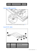
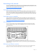
Each pair of RJ-45 patch panel 2s supports two FC connections when an FC adapter is installed. A server
blade installed in bay 1 (from the front view) occupies the bottom connector on each patch panel. For
more information, refer to the HP website (http://www.hp.com/go/bladesystem/interconnects
).
Connector Corresponds to
1 Bay 1
2 Bay 2
3 Bay 3
4 Bay 4
5 Bay 5
6 Bay 6
7 Bay 7
8 Bay 8
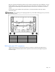
Interconnect switch and FC connections
Interconnect switches (integrated Ethernet switches) can be installed in a server blade enclosure
supporting HP ProLiant BL25p Generation 2 Server Blades. Each interconnect kit contains two interconnect
switches that reduce server-networking ports from up to 32 to as few as one, depending on the types of
server blades in the enclosure. A variety of interconnect kits are available and all are supported by the HP
ProLiant BL25p Generation 2 Server Blade. For more information, refer to the HP website
(http://www.hp.com/go/bladesystem/interconnects
).
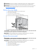
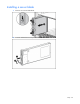
Installing server blade options
Before installing and initializing the server blade, install any server blade options, such as additional
DIMMs, hard drives, NIC mezzanine, FC mezzanine, or a processor. For server blade options installation
information, see "Hardware options installation (on page 22)."