
Manual


Setup 18
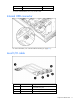
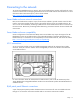
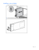
Each pair of RJ-45 patch panels provides up to four network connections per server blade bay. A server
blade installed in bay 1 (from the front view) maps to four of the bottom row Ethernet connectors. Each
consecutive server blade maps to four Ethernet connectors in the next row of connectors in a similar
manner.
For RJ-45 patch panel installation and specifications, see the documentation that ships with the
interconnect option.
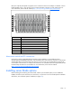
IMPORTANT: NIC numbering is for mapping purposes only. Actual NIC numbering can vary with server
blade operating systems.
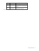
Item Connector Side
1 PXE/data NIC A
2 Data NIC* A
3 Data NIC B
4 Data NIC* B
*This NIC is available only if an optional NIC mezzanine is installed.
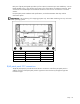
RJ-45 patch panel 2 FC connections
The RJ-45 patch panel 2 provides the same network connections as the first RJ-45 patch panel. In
addition, the front of the RJ-45 patch panel 2 supports FC SAN connectivity through the eight SFP
transceiver cages.