
User's Manual


Component identification 15
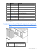
Item Component Description
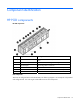
4 ASSD panel (on page 36) Air sampling smoke detection system
5 EPO button Cuts off all power to the POD and activates the EPO alarm
lamp.
6 Security panel ("Security panel
location" on page 39)
Reserved for installing interface and power requirements for
any optional security devices installed.
7 EPMS panel∗ ("EPMS panel"
on page 38)
Electrical power monitoring system
8 Humidifier ("Humidifier
(optional)" on page 44)*
Maintains the humidity inside the HP POD within a set range
to minimize static electricity.
9 Auxiliary Land power* Provides auxiliary power for the BMS or convenience outlets.
120V owner-provided power.
10 BMS panel (on page 36) Building Management System
11 Fan control (FC) panel ("Fan
control panel" on page 38)
Circuit breakers that control the fan units
12 House panel (on page 38) 120A electrical panel board providing auxiliary HP POD
electrical requirements
13 Junction Box Main input box for incoming electrical feeder cables
∗Optional component
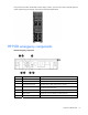
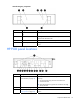
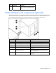
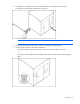
Transformer and switchboard components (optional)
NOTE: The transformer and switchboard must be a minimum of 1.2 m (48 in) away from the
HP POD.
Item Component Description
1 Switchboard Distributes power to each of the
electrical busways breakers and the
House panel