HP Performance-Optimized Datacenter User Guide Part Number 510055-001 March 2009 (First Edition)
© Copyright 2009 Hewlett-Packard Development Company, L.P. The information contained herein is subject to change without notice. The only warranties for HP products and services are set forth in the express warranty statements accompanying such products and services. Nothing herein should be construed as constituting an additional warranty. HP shall not be liable for technical or editorial errors or omissions contained herein. Confidential computer software.
Contents Site requirements .......................................................................................................................... 6 Optimum environment................................................................................................................................ 6 Location considerations .................................................................................................................... 6 Moving the HP POD ................................................
Water precautions......................................................................................................................... 31 Water temperature ........................................................................................................................ 31 Power management .................................................................................................................... 32 Electrical busway .......................................................................
Air and water heat exchanger maintenance................................................................................................ 54 Before you contact HP.............................................................................................................................. 55 HP contact information ................................................................................................................... 55 Regulatory compliance notices ................................................
Site requirements Optimum environment Specific environmental requirements must be met to provide optimum performance with minimum maintenance for your unit. HP provides the HP Performance-Optimized Datacenter Site Requirements Information document to learn about these requirements and plan your configuration more efficiently. The latest version of the guide is available on the HP website (http://www.hp.com/go/pod). Location considerations The HP POD can be located either inside or outside your facility.
• Cooling water • Power • Drain (optional) Available to connect to central facility infrastructure • BMS via BacNet protocol • Security system • Convenience outlet power • Site networking connection • Domestic water for humidifier (optional) Transformer, switchboard, and water distribution kit locations If you choose to purchase the kits, consider: • Distance from the facility utilities • Distance from the HP POD The transformer and switchboard can be installed within 3 m (10 ft) of the
Callout Connection 2 Chilled water return connection 3 Chilled water supply connection 4 IT cable portals∗ ∗There are identical IT cable portals on the left side of the HP POD. Work space requirements IMPORTANT: Failure to comply with the work space requirements can result in failed authorization to power your HP POD by local electrical inspectors. Work platform requirements NOTE: The base of the work platform should be level with the base of the HP POD.
Leveling requirements The site location for the HP POD must be level +/- 0.5 degree tolerance. Grounding requirements IMPORTANT: Before installing the HP POD, consult your local AHJ for applicable codes and to review site-specific location guidelines. The HP POD must be grounded in accordance to local electric code. HP recommends grounding the HP POD, the transformer and switchboard, and the water distribution kit to your ground grid system for full protection.
Safety considerations Safety information The HP POD has been listed to the UL 69050 as an Information Technology Product and Classified according to the National Electric Code, NFPA-70, 2008. The HP POD is not suitable for long term human occupancy. The HP POD has service access areas for periodic maintenance and service, only to be used by owner authorized personnel specifically trained in the maintenance and service of the HP POD IT components.
CAUTION: All customer supplied water fittings must be composed of carbon steel, stainless steel, or copper. Do not use cast iron, aluminum, or PVC fittings. CAUTION: During operation, avoid leaving the HP POD doors open, to minimize condensation conditions.
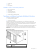
Component identification HP POD components HP POD components Item Component Description 1 Drain lines Collect water from the drain pans and removes it from the HP POD 2 Electrical busways Main source of distributing power throughout the HP POD 3 Heat exchangers Use cooling water to cool the air 4 Rear service doors Enable access to the rear of the rack-mounted components 5 Entrance doors Enable access to the front of the rack-mounted components 6 Fan units Circulate the cool air through
If any of the racks within the HP POD contain empty U space, you must use a heavy duty filler panel to avoid compromising the integrity of the hot and cold aisle temperatures. HP POD emergency components External emergency components Item Component Description 1 Fire strobe and horn Indication of a fire alarm condition within the HP POD. 2 EPO panel Contains controls and status indicators for the EPO system. 3 EPO alarm lamp (red) Activated when an EPO alarm button is pressed.
Internal emergency components Item Component Description 1 Internal fire strobe and horn (x2) Indication of a fire alarm condition within the HP POD. 2 EPO button (x2) Pressing one of these buttons cuts off all power to the HP POD and activates the EPO strobe. 3 EPO strobe Activated when an EPO button is pressed. 4 Fire alarm pull switch (x2) Pulling one of these switches activates the fire strobes and horns.
Item Component Description 4 ASSD panel (on page 36) Air sampling smoke detection system 5 EPO button Cuts off all power to the POD and activates the EPO alarm lamp. 6 Security panel ("Security panel location" on page 39) Reserved for installing interface and power requirements for any optional security devices installed.
Item Component Description 2 Transformer Transforms power from 480V at your facility to the 415V needed for the HP POD Water distribution kit components (optional) The water distribution kit is an optional component that is composed of two closed-loop systems: one for the facility water and one for the HP POD water. The water for the HP POD is supplied through the fill tank and chemically treated prior to entering the HP POD to ensure adequate water quality.
Installation HP POD contents The following items are shipped with the HP POD, and are delivered at the time of your HP POD delivery and installation.
Component Quantity Part number Side panel 50U kit 1 AN991A 50U rack bracket kit 21 AP014A Either of the following busway dropbox and PDU kits: • Single phase HP POD busway dropbox kit 30 AP912A • Single phase PDU bracket kit 88 AQ684A • Three phase HP POD busway dropbox kit 30 AS613A • Three phase HP POD PDU bracket kit 88 AQ683A 21 AP013A -or- Rack interface seal kit The HP POD is delivered with heavy duty filler panels installed in every empty U space of the
• Pipe wrench Installing the HP POD using the optional components The following steps are an overview of the installation procedure for installing a HP POD, using the transformer, switchboard, and the water distribution kit. You must obtain service professionals to connect your power and water. IMPORTANT: All wiring in and around the HP POD must be completed by a licensed electrician. IMPORTANT: All plumbing to and from the HP POD must be completed by a licensed plumber.
3. Pump domestic or industrial water into the water distribution kit closed-loop system fill tank, according to the water quality requirements (on page 30). NOTE: The HP POD pipe design is rated for a maximum pressure rating of 150 psi. 4. Verify that your facility water pressure is within the acceptable range (20-25 psi). 5. Initiate the system pumps on the water distribution kit: o Manually initiate the system pumps with the main power switch located on the pumps.
6. Open the bleeder valve on the HP POD return line. 7. When the tank is full and there is no more air coming out of the bleeder valve, close the bleeder valve on the HP POD return line. 8. Verify that your facility water pressure is within the acceptable range (20-25 psi). • NOTE: For quick reference, the water hoses are labeled with green tape and white arrows pointing in the direction of the water flow.
9. Connect the facility supply and return lines to the water distribution kit. 10. Connect the water distribution kit to your facility power source. IMPORTANT: The water supply to the humidifier must be heat-traced to prevent freezing.
11. (Optional) Connect the HP POD humidifier to the domestic or industrial water drain (1) and supply (2) lines. For more information about the humidifier, see the product documentation. 12. Perform one of the following: o If your HP POD is located inside, HP recommends connecting each of the drains to the local drain line. o If your HP POD is located outside, you can choose to connect to the local drain line, or allow the water to drain off freely in your location.
Each connection is labeled. Two of the conduits power the electrical busway breakers and one powers the house panel. 3. Turn on facility power. 4. Close the three main breakers on the switchboard.
5. Close the main breaker in the House panel on the exterior of the HP POD. 6. Close the remaining breakers in the House panel one by one, following the panel schedule on the inside of the House panel. NOTE: If you are installing a high density HP POD, you must also close the main breaker in the electrical busway 3 panel. 7. Close the main breakers in the electrical busway 1 and electrical busway 2 panels. 8.
• Test the operation of the analog and digital phone system • Verify initial IT start-up • Conduct an infrared scan of all electrical connections under the start-up IT load • Verify accurate cooling under start-up IT load • Provide the HP POD operation owner training Installation 26
Cooling system HP POD cooling system CAUTION: Contaminated supply water might cause decreased cooling capacity or disruption in service. The supply water must meet the guidelines states in the HP Performance-Optimized Datacenter Site Requirements Information document. Damage caused by contaminated supply water is not covered by the warranty. The HP POD has 12 heat exchangers that maintain temperature and cool the equipment installed in the HP POD.
2. Pull the overhead down. Condensation management CAUTION: During operation, avoid leaving the HP POD doors open, to minimize condensation conditions. Supply cooling water that is above the dewpoint inside the HP POD to reduce condensation forming on the heat exchangers, and also cold enough to maintain the cold aisle temperature setpoint.
WARNING: Any water that drains around the HP POD causes a potential slip hazard. Use caution where slip hazards are present. Water from natural condensation might form. Condensation from the heat exchangers flow to the three condensate drains across the rear of the HP POD (1). The water main drain catches any water from a water main leak (2). The humidifier drain removes excess moisture from the air (3).
Water quality requirements Water quality requirements and specifications • Closed-loop water must not contain any lime scale deposits or loose debris. • The water must have a low level of hardness, particularly a low level of carbon hardness. Additionally, the water must not be so soft that it attacks the materials with which it comes into contact. • The chilled water temperature to be supplied to the HP POD is 12º to 24ºC (55º to 75ºF). Freezing water might cause a blockage and damage to the unit.
Frost damage To avoid frost damage, the water temperature must not be allowed to fall below the minimum permissible temperature of +4 ºC (+39.2 ºF) at any point in the water cycle. The water cycle must be drained completely using compressed air before storage or transportation at freezing temperatures or below.
Power management Electrical busway The electrical busway is a modular, overhead electrical distribution system that supplies power to the HP POD IT loads. There are two electrical busways in the standard HP POD (1 and 3) and three electrical busways in the high density HP POD (1, 2, and 3). Each PDU is powered by the dropboxes attached to each of the electrical busways.
• To disable power to a single PDU, turn off the main switch on that PDU. • To disable power to a single rack, open the main breaker on the dropbox connected to the electrical busway. • To disable power to a single electrical busway, open the appropriate main breaker for that busway on the corresponding electrical busway panel outside of the HP POD. Power distribution The standard HP POD is powered by two electrical busways on the ends of the unit.
The high density HP POD includes an additional electrical busway in the center of the unit. High density HP POD Feature Specification Number of busways 3 Frequency 60Hz Amps (per breaker) 400A Neutral Ampacity (per breaker) 480A Amps derated percentage 20% Max usable amps (per busway) 320A Voltage (per busway) 415V Grounding Aluminum casing Phases 3 Rack power Power is provided to each of the rack by PDUs. The PDUs can be moved around the HP POD to support component power requirements.
Panels The following panels are on the exterior of the HP POD. Item Component Description 1 Electrical busway enclosed circuit breaker (on page 36) 400A enclosed circuit breakers that powers the electrical busways: • Two electrical busway panels are activated in the standard HP POD. • Three electrical busway panels are activated in the high density HP POD.
ASSD panel The ASSD panel draws air from the piping network inside the HP POD and monitors the smoke levels in the air. If smoke is detected, the ASSD panel automatically sends an alarm to the prewired Fire Alarm Control Panel. No user interface settings are required. Interface is established through the Fire Alarm Control Panel. For more information, see the product documentation included in the Operations & Maintenance Manual ("Component documentation" on page 9).
To enable remote access to the EPO system, switch to Bypass mode. Callout Component Description 1 Power On LED Indicates the EPO is functional, and operating in Test mode, Armed mode, or Bypass mode. 2 EPO Armed mode LED Indicates the EPO is operating in Armed mode. 3 Reset button Resets the EPO system after an EPO alarm has been triggered. 4 Three way key-operated switch Sets the EPO operating mode (Test, Armed, or Bypass).
Armed mode—Pressing a red EPO button on the POD causes the following events: • The red System Alarm/EPO Shutdown light on the EPO panel illuminates to indicate that an EPO switch has been activated. (This light remains illuminated until all EPO buttons are restored to their normal state by means of a key release mechanism, and the Reset button on the EPO panel is pressed.) • The EPO activated relay is energized and sends a signal to the EPO panel to energize the associated control relays.
Security panel location If you decide you want to install a security panel, the HP POD has a predesignated location for a security panel.
Building management system Using a building management system (BMS) NOTE: If your site does not have a BMS, then BMS data can be sent and viewed to a set IP address, communicating via Ethernet cable connected to the internal passway of the BMS Panel. HP recommends connecting the HP POD to your facility building management system (BMS), communicating through Ethernet cable connected to the internal passway of the BMS Panel. For more information, see Connecting the HP POD to the BMS (on page 40).
For more information, see the junction control system documentation included in the Operations & Maintenance Manual ("Component documentation" on page 9). Managing BMS settings from the HP POD The BMS controls can be accessed from a laptop if necessary. To access the BMS using a laptop at the HP POD, connect an Ethernet cable between a laptop and the designated BMS jack on the interior of the HP POD.
Alarm Meaning Solution Fan failure One of the fans is not working. If you are still within your service contract, contact HP service. Sensor failure One of the sensors is not working. If you are still within your service contract, contact HP service. Leak detection The drain tray senses water. Turn off the water flowing into your HP POD at the facility line. Turn off all IT components, so that the components do not overheat. If you are still within your service contract, contact HP service.
4. After a 30-second delay, the HP POD releases the suppressant gas, if the optional fire suppressant system is installed.
Optional components Additional insulation You can choose to have additional insulated paint added to your HP POD prior to shipment. The additional insulation will enable the HP POD to function properly in temperatures as low as -29°C (-20°F). Air filter sensor The air filter sensor is an optional component that, if installed, alerts you to change your air filters. The sensors are located near each of the 12 air filters. If the air filters are full and should be replaced, an alert will be sent via your BMS.
Each external panel is secured through key lock hardware. The following locations have been prewired for your own security upgrades. Callout Description 1 Prewired junction box locations 2 Card reader locations 3 Internal camera locations 4 External camera locations Transformers and switchboards HP offers several transformers and switchboards to supply your power needs.
Water distribution kit power requirements Callout Specification 1 30 AT, 30 AF, 3P 2 Within facility 480V, 3 phase power distribution equipment 3 (3)#10, (1)#10G, 1"C.
Frequently asked questions HP POD frequently asked questions Question Answer Can I keep the HP POD on the trailer? Yes, if you choose to lease the trailer from HP or if your purchase your own trailer and have the HP POD installed on your trailer prior to shipment. You must also: • Ensure that the site is stable and has been prepared correctly for the additional weight of the trailer. • Provide a work platform to access exterior panels.
Question Answer Is the HP POD weather resistant? If there is an external leak, the HP POD is weatherproof and has sufficient protection against the encroachment of water inside the HP POD. What happens if there is an internal leak? If there is an internal leak, the water collects in the condensation drain pans or the water main drain pan. The additional water present in the condensation drain pan triggers a Leak Detection alarm, sent over the BMS.
Troubleshooting HP POD troubleshooting Issue Resolution The water is not flowing, or flowing too slowly. Verify that all applicable valves are open. Inspect the water lines for blockage, unblock, or replace them as necessary. The HP POD is overheating. If the fan is not functioning, check the integrity of the electrical connection to the fan. If the electrical connection seems OK, replace the fan. If the fan is functioning, check for a kink or blockage in the water line to the heat exchanger.
Specifications HP POD specifications Features Specifications Dimensions 40 ft x 8 ft x 9.
Feature Specification Number of input circuit breakers 2: 1 per panel Protection percentage 80% Amps (per breaker) 400A Fire alarm panel connections The electrical layout of the fire alarm system is as described in the schematic drawing supplied with the HP POD.
Feature Specification Humidifier 3.
Environmental specifications Features Specifications Operating temperature -18ºC to 54ºC (0ºF to 130ºF) Non-operating temperature* 2ºC to 54ºC (35ºF to 130ºF) Transit temperature** -30ºC to 60ºC (-22ºF to 140ºF), up to 72 hours Operating humidity • 15% to 80% relative noncondensing • 26ºC (79ºF) maximum wet bulb temperature • 5 to 95% relative noncondensing • 39ºC (102ºF) maximum wet bulb temperature Non-operating humidity* Operating altitude -76.
Maintenance Periodic maintenance Perform periodic inspections of the POD to ensure there is no sign of overheating. During periodic inspections, pay special attention to electrical connections and wiring. Electrical busway maintenance Periodically tighten the electrical busway connections. HP recommends tightening the electrical busway connections every six months. Inspect the busway drop boxes for loose connections, and tighten if necessary.
Before you contact HP Be sure to have the following information available before you call HP: • Technical support registration number (if applicable) • Product serial number • Product model name and number • Product identification number • Applicable error messages • Add-on boards or hardware • Third-party hardware or software • Operating system type and revision level HP contact information For the name of the nearest HP authorized reseller: • See the Contact HP worldwide (in English) we
Regulatory compliance notices Regulatory compliance identification numbers For the purpose of regulatory compliance certifications and identification, this product has been assigned a unique regulatory model number. The regulatory model number can be found on the product nameplate label, along with all required approval markings and information. When requesting compliance information for this product, always refer to this regulatory model number.
• Low Voltage Directive 2006/95/EC • EMC Directive 2004/108/EC • Machinery Directive 98/37/EEC Compliance with these directives implies conformity to applicable harmonized European standards (European Norms) which are listed on the EU Declaration of Conformity issued by Hewlett-Packard for this product or product family. This compliance is indicated by the following conformity marking placed on the product: This marking is valid for non-Telecom products and EU harmonized Telecom products (e.g.
Chinese notice Class A equipment Korean class A notice Japanese class A notice Regulatory compliance notices 58
Acronyms and abbreviations AHJ Authority Having Jurisdiction ASHRAE American Society of Heating, Refrigerating and Air-Conditioning Engineers ASSD air sampling smoke detector BMS building management system BPMS branch power monitor system EPMS electrical power monitor system EPO emergency power off FAQ frequently asked questions FC fan control HEX heat exchanger ISO International Organization for Standardization MCS modular cooling system Acronyms and abbreviations 59
NEMA National Electrical Manufacturers Association PDU power distribution unit POD Performance-Optimized Datacenter UPS uninterruptible power system Acronyms and abbreviations 60
Index A D acceptable water quality specifications 30 air and water heat exchanger maintenance 54 air filter sensor 44, 54 alarms, BMS 41 alarms, safety and security 42 ASSD panel 13, 14, 35, 36 dimensions and weight 6 drains 28 B before you contact HP 55 BMS 40, 41 BMS alarms 41 BMS panel 14, 35, 36 BSMI notice 57 building management system 40 building management system, connecting the POD 40 C cables, FCC compliance 56 Canadian notices 56 Chinese notice 58 commissioning the POD 25 component health 10
I installation 17 installing the POD at your facility 19 insulation 44 precautions, water 31 preinstallation checklist 18 R kit contents 17 Korean notices 58 rack power 34 regulatory compliance identification numbers 56 regulatory compliance notices 56, 57 required tools 18 requirements, electrical grounding 9 requirements, leveling 9 requirements, water quality 30 requirements, work space 8 L S leak detection 28, 29 leveling requirements 9, 30 lightning protection 9 location considerations 6 operat
Index 63