HP Performance Optimized Datacenter 40c North America Maintenance and Service Guide Abstract This guide provides maintenance and service guidance for the HP Performance Optimized Datacenter 40c NA (HP POD 40c NA).
© Copyright 2013 Hewlett-Packard Development Company, L.P. The information contained herein is subject to change without notice. The only warranties for HP products and services are set forth in the express warranty statements accompanying such products and services. Nothing herein should be construed as constituting an additional warranty. HP shall not be liable for technical or editorial errors or omissions contained herein.
Contents Illustrated parts catalog ................................................................................................................. 6 Structural component identification ................................................................................................................. 6 Parts and part number identification ..................................................................................................... 6 Life safety component identification ...............................
External chilled water flow valve .................................................................................................................. 35 Removing the external chilled water flow valve .................................................................................... 36 Replacing the external chilled water flow valve ................................................................................... 36 External pressure gauge isolation valve ..................................................
Rack specifications ..................................................................................................................................... 71 Thermal and air flow performance ............................................................................................................... 71 Environmental specifications ........................................................................................................................ 71 Optional features specifications .....................
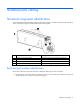
Illustrated parts catalog Structural component identification The HP POD 40c NA documentation frequently refers to the specific components of the HP POD 40c NA as shown in the following figure and described in the following table.
• Regulatory compliance identification number—This product has been assigned a unique regulatory model number and is located on the door to the control panel inside the cold aisle of the HP POD 40c NA, as shown in the following figure.
Item Component Description 4 Fire alarm manual pull* Enables manual initiation of the fire system, which includes activating the interior and exterior fire strobe lights and the optional fire suppression system 5 Fire suppression abort button* Aborts the fire suppression system. A fire suppression abort button is located next to each personnel door. *This is an optional component that might not be included.
WARNING: To avoid the risk of personal injury or loss of life, all personnel must comply with electrical warning labels when operating and maintaining the electrical panels and systems of the HP POD 40c NA.
Front view shown Callout Electrical safety label Description 1 Danger sign Provides a reminder to users that the electrical panels must be accessed only by authorized personnel 2 Disconnect label Provides the order for disconnecting all of the electrical panels 3 Caution Cautions users about isolating power from the HP POD 40c NA 4 Arc flash warning Provides a reminder to users of the danger of arc flash and required PPE Internal panel labels Front view shown Item Electrical safety label
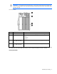
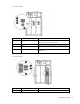
Item Electrical safety label Description 2 Panel schedule/circuit breaker table Lists the layout and designation for all circuit breakers on the panel 3 Fuse type table Lists all fuse type and sizes 4 Wire color code 415Y/240V color codes • • • • • Purple/Brown—Phase A/L1 Purple/Orange—Phase B/L2 Purple/Yellow—Phase 3/L3 Purple/White—Neutral Green and yellow—Equipment ground Control cabinet component identification Item Component Description 1 VESDA air sampling smoke detection unit VESDA
Item Component Description 7 Dual power supplies with battery backup Provides 24 V DC power to the PLC, LED lighting, and ECS systems 8 Batteries Provides 24 V DC power to the PLC and ECS system 9 Control transformers Provides to the power flow control valve 10 240/120 V transformer Provides house power to the convenience outlets — PLC The computer that controls the ECS system (located on the inside door of the control cabinet) Cooling system component identification The heat exchanger acc
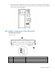
Aisle clearances Cold aisle clearance The maximum protrusion of any installed IT component directly impacts the available cold aisle clearance for removal and replacement of other IT components. Maximum component depth must follow the clear aisle distance calculations. The following figure shows how to calculate this distance. The maximum rack face-to-cold aisle wall distance is 39.5 inches.
Hot aisle clearance Hot aisle clearance is defined as the distance from the rear of the rack to the hot aisle wall. The reference distance of 2.54 cm (16 in) must be considered when selecting IT infrastructure that will populate into the hot aisle. Replaceable components Each HP POD 40c NA is unique and the specific replaceable components vary for each POD.
Removal and replacement procedures Safety considerations The HP POD 40c NA is listed to the UL 69050 standard as an Information Technology Product and Classified according to the NEC, NFPA-70, 2008. The HP POD 40c NA is not suitable for long term personnel occupancy. The safety information is specific to the people operating and maintaining the components of the HP POD 40c NA. IMPORTANT: All plumbing to and from the HP POD 40c NA must be completed by a licensed plumber.
Fire detection and suppression The fire detection and suppression system is a "Manufacturer Designed" system specifically for this HP product, in compliance with national standards. The HP standard suppression system, supplied as an optional component for the HP POD 40c NA, includes a Novec 1230 clean agent system. However, if the customer or local AHJ requires specific modifications or a replacement, HP can assist in these actions at the expense of the customer.
2. Pull the filter down through the frame channels to remove the filter. Replacing the air filter 1. Angle the filter to position the top corners in the frame channels, and then push the filter up to the top of the frame. 2. Press in the bottom corners of the filter until the locking tabs engage and the filter clicks into place.
Busway drop box The internal electrical busways provide a location to connect each of the drop boxes, which then power the PDUs. Stagger the drop boxes on the electrical busways by connecting one drop box to busway #1 and connecting the next drop box to busway #2. A staggered configuration enables load balancing with the rack equipment and is necessary to ensure redundancy. You need a socket wrench for installation.
4. Slide the hardware bracket to the right along the busway, completely disconnecting it from the busway drop box (2). WARNING: Use caution when removing and replacing the busway drop box. The drop box weighs approximately 9 kg (20 lb). 5. Rotate the busway drop box 90° so that it is perpendicular to the electrical busway, and then remove the drop box from the electrical busway (3). Replacing the busway drop box WARNING: Use caution when removing and replacing the busway drop box.
4. Secure the busway drop box to the retaining hardware bracket by using a socket wrench to insert and tighten a bolt (4). 5. Connect the PDUs to the busway drop box (1). 6. Turn the power on by closing both breakers on the busway drop box (2). Differential pressure sensor The differential pressure sensors are located in the cold aisle. You need a screwdriver for installation.
Removing the differential pressure sensor 1. Label the pressure sensor tube connection locations, and then remove the tubes from the differential pressure sensor. 2. Label the sensor wire connection locations, loosen the screws securing the sensor wires, and then remove the sensor wires. 3. Remove the two nuts (1) and two bolts (2) securing the differential pressure sensor, and then remove the differential pressure sensor. Replacing the differential pressure sensor 1.
Door position contact Door position contacts are located on all doors and cabinets. You need a screwdriver and scissors for installation. Removing the door position contact 1. Remove the two screws securing the upper magnet (1). 2. Cut the tie wrap (2) and loosen the nut on the HP POD 40c NA structure that secures the wire. 3. Pull the wire all the way through to the point of entry or ECS panel (3). Replacing the door position contact 1.
Drain pan sensor The HP POD 40c NA includes six heat exchanger condensate drains. One drain pan sensor is located in the drain tray below each set of heat exchangers. Two sensors are also located in the header drain pans, one in cooling zone 2 and one in cooling zone 5. The normally-open circuit is closed when the probes of the drain pan sensor become wet, which allows 24 VDC to travel back to the ECS panel and trigger the alarm. You need a screwdriver for installation. Removing the drain pan sensor 1.
Heat exchanger drain pan sensor -orHeader drain pan sensor Replacing the drain pan sensor 1. Position the sensor in the drain pan.
Header drain pan sensor 2. Route the wire through the flex tubing to the associated zone satellite box. 3. Connect the sensor wire to the appropriate port on the satellite box terminal. Heat exchanger drain pan sensor -orHeader drain pan sensor 4. If you are replacing a heat exchanger drain pan sensor, do the following: a. Replace the fan bank you removed, if applicable. For more information, see "Replacing the fan bank." b. Replace the fan you removed, if applicable.
ECS touchscreen The ECS touchscreen is located on the door to the control panel inside the cold aisle of the HP POD 40c NA. You need a screwdriver for installation. Removing the ECS touchscreen 1. Disconnect the cables attached to the back of the ECS touchscreen. 2. Remove the eight screws on the back of the door that secure the ECS touchscreen (1), and then push the ESC touchscreen through the front of the door to remove the ECS touchscreen (2).
Replacing the ECS touchscreen 1. Replace the ESC touchscreen through the front of the door (1), and then secure the ECS touchscreen to the back of the door with eight screws (2). 2. Connect the cables to the back of the ECS touchscreen. EPO button There are two EPO buttons, one by each personnel access door in the HP POD 40c NA. You need a screwdriver for installation.
Removing the EPO button 1. Remove the two screws securing the tamper cover (1), and then remove the tamper cover (2). 2. Remove the four screws securing the EPO button (1), and then remove the EPO button (2).
Replacing the EPO button 1. Replace the EPO button (1), and then replace the four screws that secure the EPO button (2). 2. Replace the tamper cover (1), and then replace the two screws that secure the tamper cover (2).
EPO LED indicators The ECS cabinet contains white (1, 2, 6, 7), red (1,3), yellow (1,5), and green (4) EPO LED indicators. Tools are not required for installation. Removing the EPO LED indicator 1. On the back of the ECS cabinet door, push the gray tab on the EPO LED indicator module down to release the module (1), and then pull the module out of the door (2).
2. Unscrew the EPO LED indicator bulb. Replacing the EPO LED indicator 1. Screw the new EPO LED indicator bulb into the module.
2. Push the module into the slot on the back of the ECS cabinet door until it clicks into place. EPO thermister Two EPO thermisters are located in the hot aisle, both in zone 4. While the thermisters are not technically at-temperature monitoring devices, when the hot aisle temperature reaches 60ºC (140ºF), the thermister switch closes. When both thermister switches are closed, the EPO system initiates an emergency shutdown. You need scissors for installation. Removing the EPO thermister 1.
2. Secure the thermister with tie wraps (2). External chilled water flow actuator The external chilled water flow actuator is located on top of the HP POD 40c NA. You need a wrench for installation. Removing the external chilled water flow actuator 1. Open and danger tag the associated circuit breaker in the ECS cabinet. The circuit breakers are identified on the panel schedule.
2. Remove the four bolts securing the face plate (1), and then remove the face plate (2). 3. Disconnect the power to the actuator. 4. Remove the four bolts securing the actuator (1), and then remove the actuator (2).
Replacing the external chilled water flow actuator 1. Replace the actuator (1), and then secure the actuator using four bolts (2). 2. Connect the power to the actuator. 3. Replace the actuator face plate (1), and then secure the face plate with four bolts (2). 4. Close the associated circuit breaker in the ECS cabinet. External chilled water flow valve The external chilled water flow valve is the butterfly valve located on top of the HP POD 40c NA. You need a wrench for installation.
Removing the external chilled water flow valve 1. Remove the external chilled water flow actuator. For detailed instructions, see "Removing the external chilled water flow actuator (on page 33)." 2. Remove the eight bolts surrounding the valve (1), and then remove the valve (2). Replacing the external chilled water flow valve 1. Replace the valve (1), and then secure the valve with eight bolts (2). 2. Replace the external chilled water flow actuator.
You need an adjustable wrench or an appropriately sized box wrench for installation. Removing the external pressure gauge isolation valve Loosen the connection securing the valve (1), and then remove the valve (2). Replacing the external pressure gauge isolation valve Insert the new valve (1), and then tighten the connection (2). Fan There are 18 fans per cooling zone.
CAUTION: Power must be removed from the fan power assembly before removing or replacing a fan or fan bank. You need a screwdriver for installation. Removing the fan 1. Take manual control of the fan speed in the affected zone from the ECS panel. 2. Set the fan speed to zero. 3. Unseat both power supplies from the fan power assembly.
4. Remove the three screws that secure the fan in the assembly (1), and then partially remove the fan by pulling it straight out (2). 5. Disconnect the wire. 6. Remove the fan from the assembly. Replacing the fan 1. Connect the wire. 2. Insert the fan into the assembly and push until the fan is fully seated (1). 3. Secure the fan with three screws (2). 4. Connect the power supplies to the fan power assembly. 5. Return the fan bank to the AUTO mode of operation.
Fan bank There are three fan banks per cooling zone. CAUTION: Power must be removed from the fan power assembly before removing or replacing a fan or fan bank. You need a screwdriver for installation. Removing the fan bank 1. Take manual control of the fan speed in the affected zone from the ECS panel. 2. Set the fan speed to zero. 3. Unseat both power supplies from the fan power assembly. 4. Remove the fan bank wire harness (1). 5. Remove the six screws that secure the fan bank (2).
6. Remove the fan bank by pulling it straight out (3). Replacing the fan bank 1. Insert the fan bank (1). 2. Secure the fan bank with six screws (2). 3. Replace the fan bank wire harness (3). 4. Connect the power supplies to the fan power assembly. 5. Return the fan bank to the AUTO mode of operation.
Fire strobe light The HP POD 40c NA contains an internal fire alarm strobe light in the cold aisle and an external fire alarm strobe light at the standard personnel entry door. You need a screwdriver for installation. Removing the fire strobe light 1. Remove the four screw cover plates (1). 2. Remove the four screws securing the components (2), and then disconnect the wiring. 3. Remove the electric sounder with strobe, the semi-flush plate, and the standard back box (3).
Replacing the fire strobe light 1. Assemble the standard back box, the semi-flush plate, and the electric sounder with strobe (1), and then attach the wiring. 2. Secure the components with four screws (2). 3. Attach the four screw cover plates (3). Humidifier The humidifier is located in the cold aisle humidifier bump out. You need a screwdriver for installation.
Removing the humidifier 1. Hold the drain button on the humidifier exterior until the humidifier cylinder drains completely. 2. Press the power button on the outside of the humidifier to power down the humidifier. 3. Close the water supply isolation valve on the HP POD 40c NA exterior. 4. Disconnect the water supply line to the humidifier on the HP POD 40c NA exterior to relieve the water pressure. 5. Open and danger tag the associated circuit breaker in the ECS cabinet.
10. Disconnect and remove the external electrical wiring from the housing (3). 11. Remove the four screws that secure the humidifier body to the wall (1), and then remove the humidifier (2).
Replacing the humidifier 1. Replace the humidifier (1), and then secure the humidifier to the wall with four screws (2). 2. Connect the drain (1). 3. Connect the humidifier to the water supply line (2). 4. Route and connect the external electrical wiring to the housing (3). 5. Locate the power board and connect the two internal electrical wires.
6. Replace the humidifier cover (1), and then secure the cover with four screws (2). 7. Open the water supply isolation valve on the HP POD 40c NA exterior. 8. Connect the water supply line to the humidifier on the HP POD 40c NA exterior. 9. Close the associated circuit breaker in the ECS cabinet. 10. Press the power button on the outside of the humidifier to power up the humidifier. Humidistat The humidistat is located in the cold aisle humidifier bump out.
2. Open and danger tag the associated circuit breaker in the ECS cabinet. The circuit breakers are identified on the panel schedule. 3. Detach the front panel of the humidistat from the mounting base: a. Remove the screw securing the tab in the opening (1), and then slide the tab to the open position (2). b. Use a flathead screwdriver to the press the release button (1), and then pull the front panel from the bottom to detach the panel (2). The two parts remain connected by a flat cable. 4.
a. Remove the screw securing the tab in the opening (1), and then slide the tab to the open position (2). b. Use a flathead screwdriver to the press the release button (1), and then pull the front panel from the bottom to detach the panel (2). The two parts remain connected by a flat cable. 2. Secure the mounting base to the wall using the screws provided. 3. Squeeze the two terminal cover fins to remove the terminal covers. 4.
Humidity sensor The HP POD 40c NA contains two humidity sensors, one in cooling zone 2 and one in cooling zone 5. You need a screwdriver for installation. Removing the humidity sensor 1. Remove the four screws that secure the sensor cover (1), and then remove the cover (2).
2. Loosen the sensor wires by turning the nut counter clockwise (1), remove the sensor wires from the terminal block, and then remove the sensor wires (3). 3. Remove the two screws that secure the sensor (1), and then remove the sensor (2).
Replacing the humidity sensor 1. Replace the sensor (1), and then secure the sensor with two screws (2). 2. Insert the sensor wire into the nut (1), secure the wire by turning the nut clockwise (2), and then insert the wire into the terminal block (3).
3. Replace the sensor cover (1), and then secure the cover with four screws (2). LED light Each POD contains eight LED lights. You need adhesive tape for installation. Removing the LED light You need a screwdriver for installation. 1. Disconnect power from the LED light. 2. Remove the screws (1).
3. Remove the LED light assembly (2). Replacing the LED light 1. Place the LED light where you want to secure it (1). 2. Insert the screws (2). 3. Reconnect power to the LED light. Temperature sensor (cold aisle) The HP POD 40c NA contains six temperature sensors in the cold aisle. You need a screwdriver and scissors for installation.
Removing the cold aisle temperature sensor 1. Remove the two screws that secure the sensor cover (1), and then remove the cover (2). 2. Cut the two red wires inside the sensor box. 3. For each of the five clamps securing the sensor tube to the HP POD 40c NA structure, remove the screw that secures the clamp (1), rotate the clamp (2), and then pull the clamp out to remove the clamp (3). 4. Remove the sensor tube.
Replacing the cold aisle temperature sensor 1. Replace the sensor tube, and then secure the tube with five clamps. For each clamp, replace the clamp (1), and then secure the clamp with a screw (2). 2. Splice the two sensor tube wires with the red wires inside the sensor box. 3. Replace the sensor cover (1), and then secure the cover with two screws (2).
Temperature sensor (hot aisle) The HP POD 40c NA contains six temperature sensors in the hot aisle. You need a screwdriver for installation. Removing the hot aisle temperature sensor 1. Remove the four screws that secure the sensor cover (1), and then remove the cover (2). 2. Loosen the sensor wires by turning the nut counter clockwise (1).
3. Loosen the screw securing the wires (2), and then remove the sensor wires (3). 4. Remove the two screws that secure the sensor (1), and then remove the sensor (2).
Replacing the hot aisle temperature sensor 1. Replace the sensor (1), and then secure the sensor with two screws (2). 2. Insert the sensor wires into the screw (1), and tighten the screw (2). 3. Secure the wire by turning the nut clockwise (3).
4. Replace the sensor cover (1), and then secure the cover with four screws (2). VESDA filter The VESDA filter sensor notifies you through the ECS when a filter must be changed. HP recommends that you periodically inspect and change each VESDA filter. A VESDA filter can be replaced during normal HP POD 40c NA operation. You need a screwdriver for installation. Removing the VESDA filter 1. Remove the filter cover on the front of the VESDA unit.
2. Remove the 10mm screw that secures the VESDA filter (1), and then remove the filter (2). Replacing the VESDA filter 1. Insert the new VESDA filter (1), and then replace the 10mm screw that secures the filter (2). 2. Replace the VESDA filter cover.
Periodic maintenance Periodic maintenance overview Perform periodic inspections on the components in this section to ensure that the HP POD 40c NA continues to perform within the designed parameters.
Component to be inspected Task Frequency Capable Party Condensate drain lines and p-trap Inspect and verify: Quarterly Qualified personnel • • • • Heat exchanger fans Chilled water header drain pan and lines No blockage of the drain line—internal Condensate can pass freely P-traps are intact and not leaking No blockage of the drain line—external to the site drain Clean and remove debris as necessary Inspect wiring and verify that Quarterly Qualified personnel electrical components are secure and
2. Power down the IT equipment in the zone where the leak is located. 3. Determine the affected heat exchanger. 4. Close and danger tag the supply and return valves to the affected heat exchanger. If the heat affected exchanger cannot be identified, close all the heat exchanger supply and return valves in the affected zone and open one supply valve at a time to determine the location of the leak. 5. Repair the leak or contact HP if you are still within your service contract.
Electrical Maintenance of the electrical components might require the following: • Expose personnel to high voltage. • Allow personnel to come into direct contact with high voltage. • Power down the POD during the execution of the maintenance item. You must explicitly state and acknowledge if a POD power down will be possible. If a power down is not possible, LLS inspections will be conducted and further action will be taken at your discretion.
Component to be inspected Task Frequency Capable Party Circuit breakers Annually Licensed electrician — Panel breaker operational test (open and shut). LLS inspection of breakers, disconnects, motor starters, and fuse holders (physical).
Component to be inspected Task Suppression system Suppression system test — — Frequency As required by local code Fire-pull visual and operational As required by inspection local code Fire strobe and horn visual and As required by operational inspection local code Capable Party Authorized technician Authorized technician Authorized technician HP POD 40c NA structure Component to be inspected Task Complete structure Visually inspect the structural Annually integrity.
Component to be inspected Task Frequency Capable Party EPO System Test EPO NON-FUNCTIONAL TEST Mode Key Switch Test - rotate keyed switch through all modes.
Internal UPS and rack equipment that is purchased from HP is covered by a standard HP warranty and services contract, purchased separately. • Generators • Switchgear For maintenance activities for all third party equipment purchased as part of and delivered with the HP POD 40c NA, see the Operations and Maintenance Manual for the HP Performance Optimized Datacenter 40c NA. This manual might not cover equipment purchased through Critical Facilities Services.
Specifications General specifications Features Specifications Overall dimensions • • • Weight1 Empty—16,783 kg (37,000 lb) Maximum fully loaded—46,266 kg (102,000 lb) Maximum power2 600 kW HP POD 40c NA Power input voltage 380 VAC to 415 VAC Power distribution3 8 x 200 A electrical busways Maximum rack quantity 20 racks RU per rack 50 RU RU total 1,197 RU Average capacity per rack (kW) 30 kW Peak rack capacity 69 kW Voltage to rack 200 VAC to 240 VAC Minimum quantity of PDUs per HP P
Fire alarm panel connections The electrical layout of the fire alarm system is as described in the schematic drawing supplied with the HP POD 40c NA. Water specifications The following table describes the chilled water system specifications for the HP POD 40c NA. Feature Specification Facility input temperature to the HP POD 40c NA 12ºC to 24ºC (55ºF to 75ºF) Working pressure 1,034 kPa (150 psi) HP POD 40c NA pressure drop 172.4 kPa (25 psi) HP POD 40c NA water flow rate 908.
Feature Specification Non-operating temperature* -29ºC to 54ºC (-20ºF to 130ºF) Operating humidity • • 0% to 100% external 10% to 90% non-condensing internal Non-operating humidity* • • 5% to 95% relative non-condensing 39ºC (102ºF) maximum wet bulb temperature Operating altitude -76.2 m to 3,048 m (-250 ft to 10,000 ft) Non-operating altitude -76.
Contacting HP Before you contact HP Be sure to have the following information available before you call HP: • Active Health System log (HP ProLiant Gen8 or later products) Download and have available an Active Health System log for 3 days before the failure was detected. For more information, see the HP iLO 4 User Guide or HP Intelligent Provisioning User Guide on the HP website (http://www.hp.com/go/ilo/docs).
Regulatory information Safety and regulatory compliance For safety, environmental, and regulatory information, see Safety and Compliance Information for Server, Storage, Power, Networking, and Rack Products, available at the HP website (http://www.hp.com/support/Safety-Compliance-EnterpriseProducts). Turkey RoHS material content declaration Ukraine RoHS material content declaration Warranty information HP ProLiant and X86 Servers and Options (http://www.hp.
Glossary AHJ authority having jurisdiction branch circuit The conductors and components following the last overcurrent protective device protecting a load. control transformer A transformer whose secondary supplies power to control circuit devices only (excluding loads). cover An unhinged portion of an enclosure that covers an opening. door A hinged portion of an enclosure that covers an opening.
PDU power distribution unit PLC programmable logic controller PPE personal protective equipment RU rack units structure Enclosure of sufficient size to enable entry of personnel.
Documentation feedback HP is committed to providing documentation that meets your needs. To help us improve the documentation, send any errors, suggestions, or comments to Documentation Feedback (mailto:docsfeedback@hp.com). Include the document title and part number, version number, or the URL when submitting your feedback.
Index A air filter, removing 16 air filter, replacing 17 air filters 16 authorized reseller 73 B before you contact HP 73 busway drop box, removing 18 busway drop box, replacing 19 busway drop boxes 18 C chilled water flow actuator, removing 33 chilled water flow actuator, replacing 34 chilled water flow actuators 33 chilled water flow valve, removing 35 chilled water flow valve, replacing 36 chilled water flow valves 35 compliance 74 components 6 components, identification 6 components, mechanical 6 cont
H R help resources 73 HP contact information 73 HP POD 40c NA racks 12 HP technical support 73 HP website 73 HP, contacting 73 humidifier 43, 64 humidifier, removing 43 humidifier, replacing 45 humidistat 47 humidistat, removing 47 humidistat, replacing 48 humidity sensor 49 humidity sensor, removing 50 humidity sensor, replacing 51 rack specifications 71 regulatory compliance identification numbers 74 regulatory compliance notices 74 removal and replacement procedures 15 replacement procedures 15 requir