
User Manual

Power, electrical, and controls 31
• To disable power to all racks, open the breaker for each busway on the corresponding electrical panel
on the HP POD 40c G2 exterior.
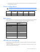
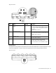
Power configurations
IMPORTANT: Different PDUs can alter the average power capacity per rack.
Configuration Number of 3-phase
PDUs per HP POD
40c G2
Number of drop
boxes per HP POD
40c G2
Average power
capacity per rack
Total HP POD 40c
G2 power capacity
Non-redundant
40 24 30 600 kW*
Redundant
40 24 20 400 kW*
*The HP POD 40c G2 is mechanically cooling limited to N=600 kW / N+1=400 kW
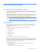
Rack power
Power is provided to each rack by PDUs and drop boxes. The PDUs are powered by the drop boxes attached
to each electrical busway. For more information about electrical busway drop boxes, see the HP
Performance Optimized Datacenter 40c G2 Maintenance and Service Guide.
Feature Specification
Rack type
HP POD 40c G2 rack
Max number of racks
20
Max U space per rack
50U
Max U space per HP POD 40c G2
1,000U
Server capacity
600 kW power capacity
Average capacity per rack
30 kW
Peak capacity per rack
69 kW
Voltage to rack
240 V
Rack configuration
Redundant/non-redundant
capabilities
Total number of PDUs
40 (two per rack)
Max power per PDU
30 A = 17 kW; 60 A = 34 kW
Max load (chilled POD cooling mode)
*
600 kW
Airflow per rack (chilled POD cooling
mode)
2,000 CFM average
*
Dependent on configuration
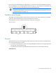
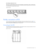
HP POD 40c G2 lighting
The HP POD 40c G2 includes eight LED lights. Four lights are located in the cold aisle and four lights are
located in the hot aisle.
A light switch is located at every personnel door. For more information on light switch locations, see "Life
safety component identification (on page 9)."