Maintenance and Service Guide HP Compaq nc8000 Business Notebook HP Compaq nw8000 Mobile Workstation Document Part Number: 333954-005 October 2006 This guide is a troubleshooting reference used for maintaining and servicing the notebook. It provides comprehensive information on identifying notebook features, components, and spare parts; troubleshooting notebook problems; and performing notebook disassembly procedures.
© Copyright 2003, 2004, 2006 Hewlett-Packard Development Company, L.P. Microsoft and Windows are U.S. registered trademarks of Microsoft Corporation. Intel and Pentium are trademarks or registered trademarks of Intel Corporation or its subsidiaries in the United States and other countries. SD Logo is a trademark of its proprietor. Bluetooth is a trademark owned by its proprietor and used by Hewlett-Packard Company under license. The information contained herein is subject to change without notice.
Contents 1 Product Description 1.1 1.2 1.3 1.4 1.5 1.6 Models. . . . . . . . . . . . . . . . . . . . . . . . . . . . . . . . . . . . 1–2 Features . . . . . . . . . . . . . . . . . . . . . . . . . . . . . . . . . . 1–13 Clearing a Password . . . . . . . . . . . . . . . . . . . . . . . . 1–16 Power Management. . . . . . . . . . . . . . . . . . . . . . . . . 1–17 External Components . . . . . . . . . . . . . . . . . . . . . . . 1–18 Design Overview. . . . . . . . . . . . . . . . . . . . . . . . . . .
Contents 3 Illustrated Parts Catalog 3.1 3.2 3.3 3.4 3.5 3.6 3.7 Serial Number Location . . . . . . . . . . . . . . . . . . . . . . 3–1 Notebook Major Components . . . . . . . . . . . . . . . . . . 3–2 Miscellaneous Plastics Kit Components . . . . . . . . . . 3–9 Miscellaneous Cable Kit Components . . . . . . . . . . 3–10 Mass Storage Devices . . . . . . . . . . . . . . . . . . . . . . . 3–11 Miscellaneous . . . . . . . . . . . . . . . . . . . . . . . . . . . . . 3–13 Sequential Part Number Listing . . .
Contents 5 Removal and Replacement Procedures 5.1 Serial Number . . . . . . . . . . . . . . . . . . . . . . . . . . . . . . 5–2 5.2 Disassembly Sequence Chart . . . . . . . . . . . . . . . . . . 5–3 5.3 Preparing the Notebook for Disassembly . . . . . . . . . 5–5 5.4 Notebook Feet . . . . . . . . . . . . . . . . . . . . . . . . . . . . . 5–11 5.5 MultiBay Device . . . . . . . . . . . . . . . . . . . . . . . . . . . 5–12 5.6 Bluetooth Board . . . . . . . . . . . . . . . . . . . . . . . . . . . 5–13 5.
Contents 6 Specifications A Connector Pin Assignments B Power Cord Requirements C Screw Listing Index vi Maintenance and Service Guide
1 Product Description The HP Compaq nc8000 Business Notebook and HP Compaq nw8000 Mobile Workstation offer advanced modularity, an Intel® Pentium® M processor with 64-bit architecture, an ATI MOBILITY RADEON 9600 Pro graphics controller with 128 or 64 MB of discrete video memory, and extensive multimedia support.
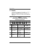
Product Description 1.1 Models Notebook model information is shown in Tables 1-1 through 1-3. Configuration code LY2Z applies to all models of the HP Compaq nc8000 Business Notebook. Configuration code MDBZ applies to all models of the HP Compaq nw8000 Mobile Workstation.
Product Description Table 1-1 HP Compaq nc8000 Business Notebook and HP Compaq nw8000 Mobile Workstation Model Naming Conventions (Continued) Key Cnc P 170 U5 80 Y Gg 10 P XXXXXX-XXX 1 2 3 4 5 6 7 8 9 10 Key Description Options 7 Integrated communication/ wireless device G = Combination modem + GB NIC N = None b = 802.11b d = 802.11a/b/g g = 802.11a/b + Bluetooth® i = 802.11b + Bluetooth j = 802.11g + Bluetooth k = 802.11a/b + Bluetooth m = 802.
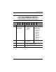
Product Description Table 1-2 HP Compaq nc8000 Business Notebook Models These HP Compaq nc8000 Business Notebook models feature the following: ■ Dual point (pointing stick and TouchPad) pointing device ■ 128-MB discrete video memory ■ 8-cell, lithium ion (Li-Ion) battery pack ■ 3-year warranty on parts and labor Cnc8000 P 170 Asia Pacific Belgium Denmark France Germany Greece Italy Cnc8000 Germany Italy Japan 1–4 P 160 U5 60 Y Gm 51 P DQ617A UUF DQ617A UUG DQ617A ABY DQ617A ABF DQ617A ABD DQ6
Product Description Table 1-2 HP Compaq nc8000 Business Notebook Models (Continued) These HP Compaq Business Notebook nc8000 models feature the following: ■ Dual point (pointing stick and TouchPad) pointing device ■ 64-MB discrete video memory ■ 8-cell, Li-Ion battery pack ■ 3-year warranty on parts and labor Cnc8000 P 170 French Canada Cnc8000 Belgium Denmark Europe France Germany Greece Iceland Italy P X5 60 W DH918U ABC 160 S5 40 W DJ242A UUG DJ242A ABY DJ242A ABB DJ242A ABF DJ242A ABD DJ24
Product Description Table 1-2 HP Compaq nc8000 Business Notebook Models (Continued) Cnc8000 P Asia Pacific Australia Belgium Brazil Czech Republic Denmark Europe France French Canada Germany Greece Hong Kong Hungary Iceland India Israel Italy Japan Japan English Korea 1–6 160 S5 40 D DN889A UUF DN889A ABG DN889A UUG DN889A AC4 DN889A AKB DN889A ABY DN889A ABB DN889A ABF DN889A ABC DN889A ABD DN889A AB7 DN889A AB5 DN889A AKC DN889A A2M DN889A ACJ DN889A ABT DN889A ABZ DN889A ABJ DN889A ACF DN889A AB
Product Description Table 1-2 HP Compaq nc8000 Business Notebook Models (Continued) Cnc8000 P 160 Belgium Denmark Europe France Germany Greece Iceland Italy P 40 D DN890A UUF DN890A ABG DN890A UUG DN890A AC4 DN890A AKB DN890A ABY DN890A ABB DN890A ABF DN890A ABC DN890A ABD DN890A AB7 DN890A AB5 DN890A AKC DN890A A2M DN890A ACJ DN890A ABT DN890A ABZ DN890A ABJ DN890A ACF DN890A AB1 Asia Pacific Australia Belgium Brazil Czech Republic Denmark Europe France French Canada Germany Greece Hong Kong Hunga
Product Description Table 1-2 HP Compaq nc8000 Business Notebook Models (Continued) Cnc8000 RP 150 Europe Cnc8000 RP 150 RP RP Belgium Czech Republic Denmark Europe France Germany Greece Hungary Iceland Israel Italy The Netherlands 1–8 W Gj 51 P X5 40 D Gi 25 P Gp 25 2 DT818P#AB2 150 X5 40 D DJ244A#UUG DJ244A#AKB DJ244A#ABY DJ244A#ABB DJ244A#ABF DJ244A#ABD DJ244A#AB7 DJ244A#AKC DJ244A#A2M DJ244A#ABT DJ244A#ABZ DJ244A#ABH Belgium Czech Republic Denmark Europe France Germany Greec
Product Description Table 1-2 HP Compaq nc8000 Business Notebook Models (Continued) Cnc8000 RP 150 People’s Republic of China Cnc8000 RP 150 RP 150 RP 150 RP 150 RP 150 Europe Cnc8000 RP 150 X5 60 W Gb 25 P Y5 40 D Gb 25 P Y5 40 W Gi 51 P Y5 60 W Gi 51 P DH936U#ABA French Canada Y5 GN 51 H Gb 51 P Gi 25 P 60 W DH936U#ABC Y5 60 W DT807P#AB1 P 140 X5 40 D DQ616A UUF DQ616A UUG DQ616A ABY DQ616A ABF DQ616A ABD DQ616A AB7 DQ616A ABZ DQ616A ABJ As
Product Description Table 1-3 HP Compaq nw8000 Mobile Workstation Models These HP Compaq nw8000 Mobile Workstation models feature the following: ■ Dual point (pointing stick and TouchPad) pointing device ■ ■ ■ ■ 128-MB discrete video memory TPM security card 8-cell, Li-Ion battery pack 3-year warranty on parts and labor Cnw8000 P 170 P 170 United States Cnw8000 Australia 1–10 Y U5 60 W Gd 10 P DU536P AB2 People’s Republic of China Taiwan DU536P AB0 Gk 10 P Gp 51 P Gp 51 2 DQ857
Product Description Table 1-3 HP Compaq nw8000 Mobile Workstation Models (Continued) These HP Compaq nw8000 Mobile Workstation models feature the following: ■ Dual point (pointing stick and TouchPad) pointing device ■ 128-MB discrete video memory ■ 8-cell, Li-Ion battery pack ■ 3-year warranty on parts and labor Cnw8000 P 170 P 170 Y P Asia Pacific Australia Belgium Europe France French Canada Germany Italy Japan Korea Hong Kong U5 60 Y DN912A UUF DN912A ABG DN912A UUG DN912A ABB DN912A ABF DN9
Product Description Table 1-3 HP Compaq nw8000 Mobile Workstation Models (Continued) Cnw8000 P 170 Asia Pacific Cnw8000 P 170 P 170 P 170 P 170 P 170 Asia Pacific Cnw8000 P 160 P 150 P P French Canada 1–12 60 W Gd 10 P U5 60 W Japan DU529P ABJ Gd 10 2 U5 60 W Gd 51 P S5 60 W Gk 51 P DQ556A ABB DQ556A ABF DQ556A ABD DQ556A ABZ Japan United Kingdom United States X5 Gm 51 P Gi 51 P Gm 51 P Gi 51 P Gm 10 P 60 W DQ556A ABJ DQ556A ABU DQ556A ABA
Product Description Table 1-3 HP Compaq nw8000 Mobile Workstation Models (Continued) Cnw8000 P 170 60 W DJ294A UUG DJ294A ABB DJ294A ABF DJ294A ABD DJ294A ABZ Belgium Europe France Germany Italy Cnw8000 U5 P 160 French Canada S5 40 W DH920U ABC Gg 51 P Spain Sweden Switzerland United Kingdom Gn 51 United States DJ294A ABE DJ294A AK8 DJ294A UUZ DJ294A ABU P DH920U ABA 1.2 Features ■ Intel Pentium M 1.7-, 1.6-, 1.5-, and 1.
Product Description 1–14 ■ Integrated Secure Digital (SD) Memory Card flash media slot ■ Integrated 10/100/1000 BASE-T Ethernet local area network (LAN) NIC with RJ-45 connector ■ Integrated wireless support for Bluetooth® LAN and Mini PCI 802.
Product Description ■ Connectors: ❏ SD Card ❏ Infrared ❏ Two Type II PC Card slots ❏ RJ-11 (modem) ❏ RJ-45 (NIC) ❏ Two Universal Serial Bus (USB) 2.
Product Description 1.3 Clearing a Password If the notebook you are servicing has an unknown password, follow these steps to clear the password. These steps also clear the CMOS memory: 1. Prepare the notebook for disassembly (refer to Section “5.3 Preparing the Notebook for Disassembly” for more information). 2. Remove the real time clock (RTC) battery (refer to Section “5.16 RTC Battery”). 3. Wait approximately 5 minutes. 4. Replace the RTC battery and reassemble the notebook. 5.
Product Description 1.4 Power Management The notebook comes with power management features that extend battery operating time and conserve power.
Product Description 1.5 External Components The external components on the front and right side of the notebook are shown below and described in Table 1-4.
Product Description Table 1-4 Front and Right-Side Components Item Component Function 1 Stereo speakers (2) Produce stereo sound. 2 Display release latch Opens the notebook. 3 Mute button Mutes the system volume. The button lights up when volume is muted. 4 Volume control buttons Increase and decrease system volume. Press the volume up button (on right) to increase sound. Press the volume down button (on left) to decrease sound.
Product Description The external components on the rear and left side are shown below and described in Table 1-5.
Product Description Table 1-5 Rear and Left-Side Components Item Component Function 1 USB connectors (2) Connect USB 1.1- and 2.0-compliant devices to the notebook using a standard USB cable. The bottom connector is a self-powered USB connector. It can be used to connect USB 1.1- and 2.0-compliant devices to the notebook using a standard USB cable, and connect an optional External MultiBay to the notebook using the External MultiBay-powered USB cable.
Product Description Table 1-5 Rear and Left-Side Components (Continued) Item Component Function 3 Power connector Connects an AC adapter or an optional Automobile Power Adapter/Charger or Aircraft Power Adapter. 4 Serial connector Connects an optional serial device. 5 Parallel connector Connects an optional parallel device, such as an external diskette drive or a printer.
Product Description The notebook keyboard components are shown below and described in Table 1-6.
Product Description Table 1-6 Keyboard Components Item Component Function 1 Windows logo key Displays the Windows Start menu. 2 fn key Executes frequently used system functions when pressed in combination with a function key or the esc key. 3 caps lock key Enables capital alphabetic character lock. 4 f1 through f12 function keys Execute indicated system functions when pressed in combination with the fn key. 5 num lock key Enables numeric lock and the internal keypad.
Product Description The notebook top components are shown below and described in Table 1-7.
Product Description Table 1-7 Top Components Item Component Function 1 Intake vents (2) Enable airflow to cool internal components. Ä 2 Power button To prevent overheating, do not obstruct vents. Using the notebook on a soft surface, such as a pillow, blanket, rug, or thick clothing, can block airflow. When the notebook is: ■ Off, press and release to turn on the notebook. ■ In Standby, press and release to exit Standby. ■ In Hibernation, press and release to exit Hibernation.
Product Description Top Components (Continued) Maintenance and Service Guide 1–27
Product Description Table 1-7 Top Components (Continued) Item Component Function 10 MultiBay light On: A drive in the MultiBay is being accessed. 11 Drive light On: One of the following integrated drives is being accessed: ■ Hard drive ■ Fixed optical drive 12 Battery light On: A battery pack is charging. Blinking: A battery pack that is the only available power source has reached a low-battery condition.
Product Description The external components on the bottom of the notebook are shown below and described in Table 1-8.
Product Description Table 1-8 Bottom Components Item Component Function 1 MultiBay Supports an optional MultiBay device, such as a drive or battery pack. 2 MultiBay release latch Allows removal of the MultiBay drive. 3 Bluetooth compartment Holds a Bluetooth device. ✎ Bluetooth is not available in all countries. 4 Docking connector Connects the notebook to an optional port replicator. 5 Optical disk drive Reads and records CD and DVD media. 6 Serial number Identifies the notebook.
Product Description 1.6 Design Overview This section presents a design overview of key parts and features of the notebook. Refer to Chapter 3, “Illustrated Parts Catalog” to identify replacement parts, and Chapter 5, “Removal and Replacement Procedures” for disassembly steps.
2 Troubleshooting Å WARNING: Only authorized technicians trained by HP should repair this equipment. All troubleshooting and repair procedures are detailed to allow only subassembly/module-level repair. Because of the complexity of the individual boards and subassemblies, do not attempt to make repairs at the component level or modifications to any printed wiring board. Improper repairs can create a safety hazard.
Troubleshooting 2.1 Computer Setup and Diagnostics Utilities The notebook features two system management utilities: ■ Computer Setup—A system information and customization utility that can be used even when your operating system is not working or does not load. This utility includes settings that are not available in Microsoft Windows. ■ Diagnostics for Windows—A system information and diagnostic utility that is used within the Windows operating system.
Troubleshooting 3. To close Computer Setup and restart the notebook: ❏ – Select File > Save Changes and Exit and press enter. or – ❏ Select File > Ignore Changes and Exit and press enter. 4. When you are prompted to confirm your action, press F10. Selecting from the File Menu Table 2-1 File Menu Select To Do This System Information ■ View identification information about the notebook, a Port Replicator, and any battery packs in the system.
Troubleshooting Selecting from the Security Menu Table 2-2 Security Menu Select To Do This Setup Password Enter, change, or delete a Setup password. The Setup password is called an administrator password in Computer Security, a program accessed from the Windows Control Panel. Power-on Password Enter, change, or delete a power-on password. DriveLock Passwords Enable/disable DriveLock; change a DriveLock User or Master password.
Troubleshooting Selecting from the Advanced Menu Table 2-3 Advanced Menu Select To Do This Language Change the Computer Setup language. Boot Options Enable/disable: ■ QuickBoot, which starts the notebook more quickly by eliminating some startup tests. If you suspect a memory failure and want to test memory automatically during startup, disable QuickBoot. ■ MultiBoot, which sets a startup sequence that can include most bootable devices and media in the system.
Troubleshooting Table 2-3 Advanced Menu (Continued) Select To Do This Device Options (continued) ■ Change the parallel port mode from Enhanced Parallel Port (EPP, the default setting) to standard, bidirectional EPP, or Enhanced Capabilities Port (ECP). ■ Set video-out mode to NTSC (default), PAL, NTSC-J, or PAL-M.* ■ Enable/disable all settings in the Intel SpeedStep window. When Disable is selected, the notebook runs in Battery Optimized mode.
Troubleshooting 2.2 Using Diagnostics for Windows When you access Diagnostics for Windows, a scan of all system components is displayed on the screen before the diagnostics window opens. You can display more or less information from anywhere within Diagnostics for Windows by selecting Level on the menu bar. Diagnostics for Windows is designed to test HP components. If HP components are tested, the results might be inconclusive. Obtaining, Saving, or Printing Configuration Information 1.
Troubleshooting Obtaining, Saving, or Printing Diagnostic Test Information 1. Access Diagnostics for Windows by selecting Start > Settings > Control Panel > Diagnostics for Windows. 2. Select the Test tab. 3. In the scroll box, select the category or device you want to test. 4. Select a test type: ❏ Quick Test—Runs a quick, general test on each device in a selected category. ❏ Complete Test—Performs maximum testing on each device in a selected category.
Troubleshooting 6. Select the Begin Testing button. 7. Select a tab to view a test report: ❏ Status tab—Summarizes the tests run, passed, and failed during the current testing session. ❏ Log tab—Lists tests run on the system, the number of times each test has run, the number of errors found on each test, and the total run time of each test. ❏ Error tab—Lists all errors found in the notebook, along with the corresponding error codes. 8.
Troubleshooting 2.3 Troubleshooting Flowcharts Table 2-4 Troubleshooting Flowcharts Overview Flowchart Description 2.1 “Flowchart 2.1—Initial Troubleshooting” 2.2 “Flowchart 2.2—No Power, Part 1” 2.3 “Flowchart 2.3—No Power, Part 2” 2.4 “Flowchart 2.4—No Power, Part 3” 2.5 “Flowchart 2.5—No Power, Part 4” 2.6 “Flowchart 2.6—No Video, Part 1” 2.7 “Flowchart 2.7—No Video, Part 2” 2.8 “Flowchart 2.8—Nonfunctioning Port Replicator” 2.9 “Flowchart 2.9—No OS Loading” 2.10 “Flowchart 2.
Troubleshooting Flowchart 2.1—Initial Troubleshooting Begin troubleshooting. N Go to “Flowchart 2.2—No Power, Part 1”. Is there power? Y N Check LED board, speaker connections. Beeps, LEDs, or error messages? N Y Go to “Flowchart 2.17—Nonfunctioning Device” All drives working? N Y Go to “Flowchart 2.6—No Video, Part 1” Is there video? (no boot) N Keyboard/ pointing device working? Y N Y Go to “Flowchart 2.
Troubleshooting Flowchart 2.2—No Power, Part 1 No power (power LED is off). Remove from Port Replicator (if applicable). N N Power up on battery power? Go to “Flowchart 2.3—No Power, Part 2” Power up on battery power? *Reset power. Y Y N N Power up on AC power? Power up on AC power? *Reset power. Y Go to “Flowchart 2.4—No Power, Part 3” Y Y Power up in Port Replicator? Done *NOTES: 1. On some models, there is a separate reset button. 2.
Troubleshooting Flowchart 2.3—No Power, Part 2 Continued from “Flowchart 2.2—No Power, Part 1” Visually check for debris in battery socket and clean if necessary. Y Done Power on? N Check battery by recharging it, moving it to another notebook, or replacing it. N Replace power supply (if applicable). Power on? Y N Done Power on? Go to “Flowchart 2.
Troubleshooting Flowchart 2.4—No Power, Part 3 Continued from “Flowchart 2.3—No Power, Part 2” Plug directly into AC outlet. Y Power LED on? Done N Reseat AC adapter in notebook and at power source. Y Power on? Done N External N Try different outlet. Power outlet active? Y Internal or external AC adapter? Replace external AC adapter. N Internal Go to “Flowchart 2.5—No Power, Part 4” Replace power cord.
Troubleshooting Flowchart 2.5—No Power, Part 4 Continued from “Flowchart 2.4—No Power, Part 3” Open notebook. Y Reseat loose components and boards and replace damaged items. Loose or damaged parts? N Close notebook and retest. N Power on? Y Done Replace the following items (if applicable) in the order given. Check notebook operation after each of the following two replacement steps: 1. Internal DC to DC converter, processor, and system board* 2.
Troubleshooting Flowchart 2.6—No Video, Part 1 No video. Port Replicator *NOTE: To change from internal to external display, use the hotkey combination. Go to “Flowchart 2.7—No Video, Part 2” Stand-alone or Port Replicator? Stand-alone Internal or external display*? Y Adjust brightness. A Adjust brightness. Press lid switch to ensure operation. Y Y Done Video OK? Done N Internal External Video OK? Done Video OK? N N Replace the following one at a time. Test after each replacement. 1.
Troubleshooting Flowchart 2.7—No Video, Part 2 Continued from “Flowchart 2.6—No Video, Part 1” Remove notebook from Port Replicator, if connected. Adjust display brightness. Check brightness of external monitor. N Y Go to “A” in “Flowchart 2.6—No Video, Part 1” Video OK? Y Done Video OK? N Verify that notebook is properly seated in Port Replicator, and check for bent pins on cable and for secure monitor connection. Try another external monitor.
Troubleshooting Flowchart 2.8—Nonfunctioning Port Replicator Nonfunctioning Port Replicator. Reseat power cord in Port Replicator and power outlet. Check voltage setting on Port Replicator. Reinstall notebook into Port Replicator. Y Reseat monitor cable connector at Port Replicator. Port Replicator operating? N Y Port Replicator operating? N Remove notebook, reseat all internal parts, and replace any damaged items in Port Replicator.
Troubleshooting Flowchart 2.9—No OS Loading No OS loading.* Reseat power cord in Port Replicator and power outlet. No OS loading from hard drive, go to “Flowchart 2.10—No OS Loading, Hard Drive, Part 1” No OS loading from diskette drive, go to “Flowchart 2.13—No OS Loading, Diskette Drive” No OS loading from CD- or DVD-ROM drive, go to “Flowchart 2.14—No OS Loading, CD- or DVD-ROM Drive”. No OS loading from network, go to “Flowchart 2.
Troubleshooting Flowchart 2.10—No OS Loading, Hard Drive, Part 1 OS not loading from hard drive. Y Go to “Flowchart 2.11—No OS Loading, Hard Drive, Part 2” Nonsystem disk message? N Reseat external hard drive. Y OS loading? Done N N Boot from CD? N Y Go to “Flowchart 2.13—No OS Loading, Diskette Drive” Boot from diskette? Check the Setup utility for correct booting order. Y N Change boot priority through the Setup utility and reboot.
Troubleshooting Flowchart 2.11—No OS Loading, Hard Drive, Part 2 Continued from “Flowchart 2.10—No OS Loading, Hard Drive, Part 1” Reseat hard drive. N 1. Replace hard drive. 2. Replace system board. CD or diskette in drive? Y Hard drive accessible? Y Done N Remove diskette and reboot. Run FDISK. Y Boot from hard drive? N Done N Create partition, then format hard drive to bootable C:\ prompt. Hard drive partitioned? Y N N Go to “Flowchart 2.
Troubleshooting Flowchart 2.12—No OS Loading, Hard Drive, Part 3 Continued from “Flowchart 2.11—No OS Loading, Hard Drive, Part 2” N System files on hard drive? Install OS and reboot. Y Y Y Virus on hard drive? OS loading from hard drive? Clean virus. N Done N Y Run SCANDISK and check for bad sectors. Diagnostics on diskette? Replace hard drive. N N Can bad sectors be fixed? Run diagnostics and follow recommendations. Replace hard drive. Y N Fix bad sectors.
Troubleshooting Flowchart 2.13—No OS Loading, Diskette Drive Y OS not loading from diskette drive. OS loading? Reseat diskette drive. Done N N Y Install bootable diskette and reboot notebook. Bootable diskette in drive? Nonsystem disk message? N Y N Check diskette for system files. Try different diskette. Go to “Flowchart 2.17—Nonfunctioning Device” Boot from another device? Y Y N Diskette drive enabled in the Setup utility? 1. Replace diskette drive. 2. Replace system board.
Troubleshooting Flowchart 2.14—No OS Loading, CD- or DVD-ROM Drive Y No OS loading from CD- or DVD-ROM Drive. N Bootable disc in drive? Disc in drive? Y N Install bootable disc. Install bootable disc and reboot notebook. Try another bootable disc. Y Boots from CD or DVD? Done N Y Reseat drive. Boots from CD or DVD? Done N N Go to “Flowchart 2.17—Nonfunctioning Device” Booting from another device? Y Y Booting order correct? N Clear CMOS. Refer to “Section 1.
Troubleshooting Flowchart 2.15—No Audio, Part 1 Y Turn up audio internally or externally. No audio. Audio? Done N Y Notebook in Port Replicator (if applicable)? N Go to “Flowchart 2.16—No Audio, Part 2” Internal audio? Undock N Y Replace the following Port Replicator components one at a time, as applicable. Check audio status after each change. Go to “Flowchart 2.16—No Audio, Part 2” 1. Port Replicator audio cable 2. Audio cable 3. Speaker 4. Port Replicator audio board 5. Backplane board 6.
Troubleshooting Flowchart 2.16—No Audio, Part 2 Continued from “Flowchart 2.15—No Audio, Part 1” N Audio driver in OS configured? Reload audio drivers. Y N Correct drivers for application? Load drivers and set configuration in OS. Y Connect to external speaker. N Audio? Y Replace audio board and speaker connections in notebook (if applicable). Y Audio? Done N 1. Replace internal speakers. 2. Replace audio board (if applicable). 3. Replace system board.
Troubleshooting Flowchart 2.17—Nonfunctioning Device Nonfunctioning device. Reseat device. Unplug the nonfunctioning device from the notebook, and inspect cables and plugs for bent or broken pins or other damage. Y Clear CMOS. Any physical device detected? Fix or replace broken item. Replace hard drive. Go to “Flowchart 2.9—No OS Loading” N Reattach device. Close notebook, plug in power, and reboot. N Device boots properly? N Replace NIC. If integrated NIC, replace system board.
Troubleshooting Flowchart 2.18—Nonfunctioning Keyboard Keyboard not operating properly. Connect notebook to good external keyboard. N Replace system board. External device works? Y Reseat internal keyboard connector (if applicable). N Replace internal keyboard or cable. OK? Y Y Done OK? Done N Replace system board.
Troubleshooting Flowchart 2.19—Nonfunctioning Pointing Device Pointing device not operating properly. Connect notebook to good external pointing device. N Replace system board. External device works? Y Reseat internal pointing device connector (if applicable). N Replace internal pointing device or cable. OK? Y Y Done OK? Done N Replace system board.
Troubleshooting Flowchart 2.20—No Network/Modem Connection No network or modem connection. N Network or modem jack active? Replace jack or have jack activated. Y Y Connect to nondigital line. Digital line? N Y N NIC/modem configured in OS? Reload drivers and reconfigure. Done OK? N Y Disconnect all power from the notebook and open. Replace NIC/modem (if applicable). Y Reseat NIC/modem (if applicable). OK? Done N Replace system board.
3 Illustrated Parts Catalog This chapter provides an illustrated parts breakdown and a reference for spare part numbers and option part numbers. 3.1 Serial Number Location When ordering parts or requesting information, provide the notebook serial number and model number located on the bottom of the notebook.
Illustrated Parts Catalog 3.
Illustrated Parts Catalog Table 3-1 Spare Parts: Notebook Major Components Spare Part Number Item Description 1 Display assemblies 15.0-inch, UXGA+, TFT 15.0-inch, SXGA+, TFT 15.
Illustrated Parts Catalog Notebook Major Components (Continued) 3–4 Maintenance and Service Guide
Illustrated Parts Catalog Table 3-1 Spare Parts: Notebook Major Components (Continued) Item 6a 6b Description Spare Part Number Miscellaneous Cable Kit, includes: 345056-001 Modem cable Bluetooth cable 7 Modem board 325521-001 8 Fan assembly 345065-001 9 Heat sink (includes grease) 345067-001 10 Memory expansion boards, 333-MHz 1024-MB (1.0-GB) 512-MB 256-MB 11 Processors (include thermal grease) Intel Pentium M (Banias) processor, 1.7 GHz Intel Pentium M (Banias) processor, 1.
Illustrated Parts Catalog Notebook Major Components (Continued) 3–6 Maintenance and Service Guide
Illustrated Parts Catalog Table 3-1 Spare Parts: Notebook Major Components (Continued) Spare Part Number Item Description 14 Mini PCI communications boards 802.11a/b/g LAN NIC 802.11b/g LAN NIC 802.11b W500 modem board (for use in Japan) 802.11b wireless LAN (MOW) 802.11b wireless LAN (ROW) 802.11b/g wireless modem (MOW) 802.
Illustrated Parts Catalog Table 3-1 Spare Parts: Notebook Major Components Item Description Spare Part Number *Not illustrated.
Illustrated Parts Catalog 3.3 Miscellaneous Plastics Kit Components Miscellaneous Plastics Kit Components Table 3-2 Miscellaneous Plastics Kit Components Spare Part Number 345066-001 Item Description 1 Left and right display hinges 2 RTC battery 3 Mini PCI communications board shield 4 Bluetooth cover 5 Battery bezel 6 Hard drive cover 7 Notebook feet (4) * Integrated smart card bezel *Not illustrated.
Illustrated Parts Catalog 3.
Illustrated Parts Catalog 3.
Illustrated Parts Catalog Table 3-4 Mass Storage Devices Spare Part Number Information (Continued) Item Description 2 Optical drives Spare Part Number 24X Max DVD+RW/R and CD-RW Combo Drive 8X Max DVD-ROM Drive 24X Max DVD/CD-RW Combo Drive 24X Max CD-ROM Drive 3 MultiBay devices 1.
Illustrated Parts Catalog 3.
Illustrated Parts Catalog 3.
Illustrated Parts Catalog Table 3-6 Spare Parts: Sequential Part Number Listing (Continued) Spare Part Number Description 325526-001 802.
Illustrated Parts Catalog Table 3-6 Spare Parts: Sequential Part Number Listing (Continued) Spare Part Number Description 341520-121 Keyboard (including pointing stick) - French Canada 341520-131 Keyboard (including pointing stick) - Portugal 341520-141 Keyboard (including pointing stick) - Turkey 341520-161 Keyboard (including pointing stick) - Latin America 341520-171 Keyboard (including pointing stick) - Saudi Arabia 341520-201 Keyboard (including pointing stick) - Brazil 341520-211 Keybo
Illustrated Parts Catalog Table 3-6 Spare Parts: Sequential Part Number Listing (Continued) Spare Part Number Description 345058-001 Display assembly, 15.0-inch, XGA, TFT 345059-001 Display assembly, 15.0-inch, SXGA+, TFT 345060-001 Display assembly, 15.
Illustrated Parts Catalog Table 3-6 Spare Parts: Sequential Part Number Listing (Continued) Spare Part Number Description 349242-001 24X Max DVD+RW/R and CD-RW combo drive 349243-001 24X Max DVD/CD-RW combo drive 353395-001 Intel Pentium M (Dothan) processor, 2.0 GHz 356596-001 Intel Pentium M (Dothan) processor, 1.6 GHz 356597-001 Intel Pentium M (Dothan) processor, 1.7 GHz 359636-001 Intel Pentium M (Dothan) processor, 1.5 GHz 360663-001 Battery pack, 8-cell, 4.
4 Removal and Replacement Preliminaries This chapter provides essential information for proper and safe removal and replacement service. 4.1 Tools Required You need the following tools to complete the removal and replacement procedures: ■ Magnetic screw driver ■ Phillips P0 screw driver ■ Torx8 screw driver ■ Torx7 pin bit screw driver computer models have two Torx7 with pin security screws ✎ Some (M2.0×4.0) securing the Mini PCI communications board to the computer.
Removal and Replacement Preliminaries 4.2 Service Considerations The following sections include some of the considerations that you should keep in mind during disassembly and assembly procedures. you remove each subassembly from the notebook, place the ✎ As subassembly (and all accompanying screws) away from the work area to prevent damage. Plastic Parts Using excessive force during disassembly and reassembly can damage plastic parts. Use care when handling the plastic parts.
Removal and Replacement Preliminaries 4.3 Preventing Damage to Removable Drives Removable drives are fragile components that must be handled with care. To prevent damage to the notebook, damage to a removable drive, or loss of information, observe the following precautions: ■ Before removing or inserting a hard drive, shut down the notebook. If you are unsure whether the notebook is off or in hibernation, turn the notebook on, then shut it down.
Removal and Replacement Preliminaries 4.4 Preventing Electrostatic Damage Many electronic components are sensitive to electrostatic discharge (ESD). Circuitry design and structure determine the degree of sensitivity. Networks built into many integrated circuits provide some protection, but in many cases the discharge contains enough power to alter device parameters or melt silicon junctions.
Removal and Replacement Preliminaries 4.5 Packaging and Transporting Precautions Use the following grounding precautions when packaging and transporting equipment: ■ To avoid hand contact, transport products in static-safe containers, such as tubes, bags, or boxes. ■ Protect all electrostatic-sensitive parts and assemblies with conductive or approved containers or packaging. ■ Keep electrostatic-sensitive parts in their containers until the parts arrive at static-free workstations.
Removal and Replacement Preliminaries 4.6 Workstation Precautions Use the following grounding precautions at workstations: 4–6 ■ Cover the workstation with approved static-shielding material (refer to Table 4-2). ■ Use a wrist strap connected to a properly grounded work surface and use properly grounded tools and equipment. ■ Use conductive field service tools, such as cutters, screwdrivers, and vacuums.
Removal and Replacement Preliminaries 4.7 Grounding Equipment and Methods Grounding equipment must include either a wrist strap or a foot strap at a grounded workstation. ■ When seated, wear a wrist strap connected to a grounded system. Wrist straps are flexible straps with a minimum of one megohm ±10% resistance in the ground cords. To provide proper ground, wear a strap snugly against the skin at all times. On grounded mats with banana-plug connectors, connect a wrist strap with alligator clips.
Removal and Replacement Preliminaries Table 4-1 shows how humidity affects the electrostatic voltage levels generated by different activities.
5 Removal and Replacement Procedures This chapter provides removal and replacement procedures. There are 62 screws in eight different sizes that must be removed, replaced, and loosened when servicing the notebook. Make note of each screw size and location during removal and replacement. Refer to Appendix C, “Screw Listing” for detailed information on screw sizes, locations, and usage.
Removal and Replacement Procedures 5.1 Serial Number Report the notebook serial number to HP when requesting information or ordering spare parts. The serial number is located on the bottom of the notebook.
Removal and Replacement Procedures 5.2 Disassembly Sequence Chart Use the chart below to determine the section number to be referenced when removing notebook components. Disassembly Sequence Chart Section Description 5.3 Preparing the notebook for disassembly Battery pack Hard drive # of Screws Removed 0 1 to remove 4 screws and 2 alignment pins to disassemble 5.4 Notebook feet 0 5.5 MultiBay device 0 5.6 Bluetooth board 3 5.7 Integrated smart card 0 5.8 Optical drive 1 5.
Removal and Replacement Procedures Disassembly Sequence Chart (Continued) Section Description # of Screws Removed 5.20 Speaker 6 5.21 TouchPad 3 5.22 Fan assembly 4 5.
Removal and Replacement Procedures 5.3 Preparing the Notebook for Disassembly Before you begin any removal or installation procedures: 1. Save your work, exit all applications, and shut down the notebook. If you are not sure whether the notebook is off or in hibernation, briefly press the power button. If your work returns to the screen, save your work, exit all applications, and then shut down the notebook. 2. Disconnect all external devices connected to the notebook. 3. Disconnect the power cord.
Removal and Replacement Procedures Spare Part Number Information Battery pack, 8-cell, 4.4 Wh, Li-Ion Battery pack, 8-cell, 4.8AHR 338669-001 360663-001 4. Remove the battery pack by following these steps: a. Turn the notebook upside down with the front facing you. b. Slide and hold the battery release latch 1 toward the back of the notebook. c. Use the notch in the battery pack to slide the battery pack to the right 2. d. Remove the battery pack.
Removal and Replacement Procedures 5. Remove the battery bezel by sliding it down and off of the battery pack. battery bezel is included in the Miscellaneous Plastics Kit, ✎ The spare part number 345066-001. Removing the Battery Bezel Reverse the above procedure to install the battery pack and battery bezel.
Removal and Replacement Procedures 6. Remove the hard drive by following these steps: Spare Part Number Information Hard drives (includes hard drive bezel and frame) 80-GB 5400-rpm 60-GB 5400-rpm 40-GB 5400-rpm 60-GB 7200-rpm (all models) (all models) (all models) (nw8000 only) 345632-001 345631-001 345630-001 345855-001 a. Turn the notebook upside down with the front facing you. b. Remove the T8M2.0×6.0 hard drive cover screw 1. c. Slide and hold the tab on the hard drive cover to the left 2. d.
Removal and Replacement Procedures e. Use the Mylar tab 1 to slide the hard drive to the right 2 to disconnect it from the system board. f. Lift the hard drive straight up to remove it 3.
Removal and Replacement Procedures g. Remove the two T5M2.5×4.0 screws 1 and the two PM3.0×3.5 screws 2 that secure the hard drive to the hard drive frame. h. Use a 4.0-mm socket to remove the two M2.0×10.0 alignment pins 3 that secure the hard drive to the hard drive frame. i. Remove the hard drive 4 from the hard drive frame. j. Remove the hard drive connector 5 from the hard drive. Disassembling the Hard Drive Reverse the above procedure to assemble and install the hard drive.
Removal and Replacement Procedures 5.4 Notebook Feet The notebook feet are adhesive-backed rubber pads. The feet are included in the Miscellaneous Plastics Kit, spare part number 345066-001. The feet attach to the base enclosure as illustrated below.
Removal and Replacement Procedures 5.5 MultiBay Device Spare Part Number Information 1.44-MB diskette drive 24X Max CD-ROM Drive 8X Max DVD+RW/R and CD-RW Combo Drive 24X Max DVD+RW/R and CD-RW Combo Drive 135233-001 228746-001 251292-001 344256-001 1. Prepare the notebook for disassembly (refer to Section 5.3). 2. Turn the notebook upside down with the left side facing you. 3. Slide and hold the MultiBay release latch toward you 1. 4.
Removal and Replacement Procedures 5.6 Bluetooth Board Spare Part Number Information Bluetooth board (includes cable) 348277-001 1. Prepare the notebook for disassembly (refer to Section 5.3). 2. Turn the notebook upside down with the left side facing you. 3. Remove the T8M2.0×6.0 screw 1 that secures the Bluetooth cover to the notebook. 4. Lift the cover straight up to remove it 2. Bluetooth cover is included in the Miscellaneous Plastics Kit, ✎ The spare part number 345066-001.
Removal and Replacement Procedures 5. Disconnect the Bluetooth cable from the Bluetooth board 1 and the system board 2. Bluetooth cable is included with the Bluetooth board and is ✎ The also included in the Miscellaneous Cables Kit, spare part number 345056-001. 6. Remove the two PM1.5×3.0 screws 3 that secure the Bluetooth board to the Bluetooth cover. 7. Remove the board from the cover 4. Removing the Bluetooth Board Reverse the above procedure to install the Bluetooth board.
Removal and Replacement Procedures 5.7 Integrated Smart Card Spare Part Number Information Integrated smart card 379336-001 ✎ The integrated smart card is located in the bottom PC Card slot. 1. Prepare the notebook for disassembly (refer to Section 5.3). 2. Remove any PC Card or spacer from the top PC Card slot. 3. Using a flat-bladed tool, pry the smart card bezel off of the notebook 1. The bezel releases from the notebook with a small amount of force. 4. Remove the bezel from the notebook 2.
Removal and Replacement Procedures integrated smart card bezel is included in the Miscellaneous ✎ The Plastics Kit, spare part number 345066-001. 5. Eject the smart card from the notebook using a flat-bladed tool to press the small metal eject tab 1 to the left of the smart card. 6. Remove the card from the slot 2. Removing the Smart Card Reverse the above procedure to install the integrated smart card.
Removal and Replacement Procedures 5.8 Optical Drive Spare Part Number Information 24X Max DVD+RW/R and CD-RW Combo Drive 8X Max DVD-ROM Drive 24X Max DVD/CD-RW Combo Drive 24X Max CD-ROM Drive 349242-001 349241-001 349243-001 349240-001 1. Prepare the notebook for disassembly (refer to Section 5.3). 2. Turn the notebook upside down with the right side facing you. 3. Remove the T8M2.0×6.0 screw 1 that secures the optical drive to the notebook. 4.
Removal and Replacement Procedures 5.
Removal and Replacement Procedures 3. Remove the T8M2.×6.0 screw that secures the keyboard to the notebook.
Removal and Replacement Procedures 4. Turn the notebook right-side up with the front facing you. 5. Open the notebook. 6. Slide the four tabs 1 on the top edge of the keyboard toward you. 7. Lift the rear edge of the keyboard up and swing it toward you 2 until it rests on the palm rest.
Removal and Replacement Procedures 8. Release the zero insertion force (ZIF) connector 1 to which the pointing stick cable is attached and disconnect the cable 2. 9. Release the ZIF connector 3 to which the keyboard cable is attached and disconnect the cable 4. Disconnecting the Keyboard Cables 10. Remove the keyboard. Reverse the above procedure to install the keyboard.
Removal and Replacement Procedures 5.10 Memory Expansion Board Spare Part Number Information 1024 MB (1.0 GB), 333 MHz 512 MB, 333 MHz 256 MB, 333 MHz 336579-001 336578-001 336577-001 1. Prepare the notebook for disassembly (refer to Section 5.3). 2. Release the keyboard (refer to Section 5.9). 3. Spread the retaining tabs 1 that secure the memory expansion board to the socket. The free end of the board rises. 4. Pull the board away from the socket at a 45-degree angle 2.
Removal and Replacement Procedures 5.11 Modem Board Spare Part Number Information Modem board 325521-001 1. Prepare the notebook for disassembly (refer to Section 5.3). 2. Release the keyboard (refer to Section 5.9). 3. Remove the two T8M2.0×4.0 screws 1 that secure the modem board to the notebook. 4. Lift up on the right side of the modem board 2 to disconnect the board from the system board.
Removal and Replacement Procedures 5. Turn the modem board upside down 1. 6. Disconnect the modem cable 2 from the modem. Disconnecting the Modem Board Cable 7. Remove the modem board. Reverse the above procedure to install the modem board. 5.12 Mini PCI Communications Board Spare Part Number Information 802.11a/b/g LAN NIC 802.11b/g LAN NIC 802.11b W500 modem board (for use in Japan) 802.11b wireless LAN (MOW) 802.11b wireless LAN (ROW) 802.11b/g wireless modem (MOW) 802.
Removal and Replacement Procedures computer models have two Torx7 with pin security screws ✎ Some (M2.0×4.0) securing the Mini PCI communications board to the computer. A T7 pin bit screw driver is required to remove the Mini PCI communications board on these computer models. 3. Remove the two T8M2.0×4.0 screws 1 that secure the Mini PCI communications board shield to the notebook. 4. Lift up on the left side of the shield 2 and slide it to the left 3 to remove it.
Removal and Replacement Procedures 5. Disconnect the two antenna cables 1 from the board. Make note of which cable connects to which terminal. 6. Spread the retaining tabs 2 that secure the Mini PCI communications board to the socket. The free end of the board rises. 7. Pull the board away from the socket at a 45-degree angle 3. Removing the Mini PCI Communications Board 8. Remove the Mini PCI communications board. Reverse the above procedure to install the Mini PCI communications board.
Removal and Replacement Procedures 5.13 Heat Sink Spare Part Number Information Heat sink (includes grease) 345067-001 1. Prepare the notebook for disassembly (refer to Section 5.3). 2. Release the keyboard (refer to Section 5.9). 3. Remove the five T8M2.0×4.0 screws 1 that secure the heat sink to the notebook. 4. Lift the front edge of the heat sink 2 to unseat the adhesive grip of the thermal grease on the processor. 5.
Removal and Replacement Procedures clean any thermal grease residue from the heat sink 1 ✎ Carefully and processor surfaces 2 each time you remove the heat sink. Apply new thermal grease to both surfaces. Removing the Thermal Grease From the Heat Sink and Processor Reverse the above procedure to install the heat sink.
Removal and Replacement Procedures 5.14 Processor Spare Part Number Information Processors (include grease) Intel Pentium M (Banias) processor, 1.7 GHz Intel Pentium M (Banias) processor, 1.6 GHz Intel Pentium M (Banias) processor, 1.5 GHz Intel Pentium M (Banias) processor, 1.4 GHz Intel Pentium M (Dothan) processor, 1.5 GHz Intel Pentium M (Dothan) processor, 1.6 GHz Intel Pentium M (Dothan) processor, 1.7 GHz Intel Pentium M (Dothan) processor, 1.8 GHz Intel Pentium M (Dothan) processor, 2.
Removal and Replacement Procedures 4. Use a flat-bladed screwdriver to turn the processor locking screw one-quarter turn counterclockwise 1. 5. Remove the processor from the system board socket 2. that the gold triangle 3 on the processor should be aligned ✎ Note in the front left corner when you install the processor. Removing the Processor Reverse the above procedure to install the processor.
Removal and Replacement Procedures 5.15 LED Switch Cover Spare Part Number Information LED switch cover 345063-001 1. Prepare the notebook for disassembly (refer to Section 5.3). 2. Turn the notebook upside down with the rear facing you. 3. Remove the T8M2.0×6.0 screw that secures the LED switch cover to the notebook.
Removal and Replacement Procedures 4. Turn the notebook right-side up with the front facing you. 5. Open the notebook. 6. Lift the left 1 and right 2 sides of the LED switch cover to disengage the cover from the notebook. 7. Remove the LED switch cover. Removing the LED Switch Cover Reverse the above procedure to install the LED switch cover.
Removal and Replacement Procedures 5.16 RTC Battery RTC battery is included in the Miscellaneous Plastics Kit, ✎ The spare part number 345066-001. 1. Prepare the notebook for disassembly (refer to Section 5.3). 2. Remove the LED switch cover (refer to Section 5.15). 3. Disconnect the RTC battery cable 1 from the system board. 4. Slide the RTC battery out of the clips in the top cover 2 and remove the battery. Removing the RTC Battery Reverse the above procedure to install the RTC battery.
Removal and Replacement Procedures 5.17 Security Module (TPM) Spare Part Number Information Security Module (TPM) 345856-001 1. Prepare the notebook for disassembly (refer to Section 5.3). 2. Remove the LED switch cover (refer to Section 5.15). 3. Remove the PM3.5×3.0 screw 1 that secures the security card to the system board. 4. Lift the security module straight up 2 to disconnect it from the system board. Removing the TPM Security Module Reverse the above procedure to install the security card.
Removal and Replacement Procedures 5.18 Display Assembly Spare Part Number Information 15.0-inch, UXGA, TFT 15.0-inch, SXGA+, TFT 15.0-inch, XGA, TFT 345060-001 345059-001 345058-001 1. Prepare the notebook for disassembly (refer to Section 5.3). 2. Remove the keyboard (refer to Section 5.9). 3. Disconnect the wireless antenna cables from the Mini PCI wireless communications board (refer to Section 5.12). 4. Remove the LED switch cover (refer to Section 5.15). 5.
Removal and Replacement Procedures 7. Position the notebook with the rear facing toward you. 8. Remove the two T8M2.0×6.0 screws 1 that secure the display hinge covers to the notebook. 9. Remove the two T8M2.0×6.0 screws 2 that secure the display assembly to the notebook.
Removal and Replacement Procedures 10. Lift the display assembly straight up 1 to remove it from the notebook. 11. If necessary, remove the display hinge covers 2 from the display assembly. display hinge covers are included in the Miscellaneous ✎ The Plastics Kit, spare part number 345066-001. Removing the Display Assembly Reverse the above procedure to install the display assembly.
Removal and Replacement Procedures 5.19 Top Cover Spare Part Number Information Top cover (includes TouchPad and speaker) 345061-001 1. Prepare the notebook for disassembly (refer to Section 5.3). 2. Remove the keyboard (refer to Section 5.9). 3. Remove the LED switch cover (refer to Section 5.15). 4. Remove the display assembly (refer to Section 5.18). 5. Turn the notebook upside down with the front facing you. 6. Remove the 17 T8M2.0×6.0 screws that secure the top cover to the notebook.
Removal and Replacement Procedures 7. Turn the notebook right-side up with the front facing you. 8. Remove the TM2.0×4.0 screw 1 near the fan that secures the top cover to the notebook. 9. Lift the front edge of the top cover 2 until the speaker cable 3, TouchPad cable 4, and microphone cable 5 are accessible.
Removal and Replacement Procedures 10. Disconnect the speaker 1 and microphone cables 2. 11. Release the ZIF connector 3 to which the TouchPad cable is attached and disconnect the TouchPad cable 4 from the system board. Disconnecting the Top Cover Cables 12. Remove the top cover. Reverse the above procedure to install the top cover.
Removal and Replacement Procedures 5.20 Speaker speaker is included with the top cover, spare part number ✎ The 345061-001. 1. Prepare the notebook for disassembly (refer to Section 5.3) and remove the following components: ❏ Keyboard (refer to Section 5.9) ❏ LED switch cover (refer to Section 5.15) ❏ Display assembly (refer to Section 5.18) ❏ Top cover (refer to Section 5.19) 2. Turn the top cover upside down with the rear facing you. 3. Remove the five T8M2.0×4.0 screws 1 and one T8M2.0×6.
Removal and Replacement Procedures 5.21 TouchPad TouchPad and bracket are included with the top cover, spare ✎ The part number 345061-001. 1. Prepare the notebook for disassembly (refer to Section 5.3) and remove the following components: ❏ Keyboard (refer to Section 5.9) ❏ LED switch cover (refer to Section 5.15) ❏ Display assembly (refer to Section 5.18) ❏ Top cover (refer to Section 5.19) ❏ Speaker (refer to Section 5.20) 2. Remove the three Torx T8M2.0×3.
Removal and Replacement Procedures 4. Remove the bracket. 5. Remove the TouchPad 1 from the top cover. 6. Release the ZIF connector 2 to which the TouchPad cable is attached and disconnect the cable 3. Removing the TouchPad Reverse the above procedure to install the TouchPad and bracket.
Removal and Replacement Procedures 5.22 Fan Assembly Spare Part Number Information Fan assembly 345065-001 1. Prepare the notebook for disassembly (refer to Section 5.3) and remove the following components: 5–44 ❏ Keyboard (refer to Section 5.9) ❏ Heat sink (refer to Section 5.13) ❏ LED switch cover (refer to Section 5.15) ❏ Display assembly (refer to Section 5.18) ❏ Top cover (refer to Section 5.
Removal and Replacement Procedures 2. Disconnect the fan cable 1. 3. Remove the T8M2.0×4.0 screw 2 that secures the fan assembly to the notebook. 4. Remove the fan assembly 3 from the notebook. 5. Remove the three PM1.5×4.0 screws 4 that secure the fan to the fan housing. 6. Remove the fan 5. Removing the Fan Reverse the above procedure to install the fan.
Removal and Replacement Procedures 5.23 System Board Spare Part Number Information System board with 128 MB of video memory System board with 64 MB of video memory ✎ 349206-001 345064-001 Both system boards include thermal grease. replacing the system board, ensure that the following ✎ When components are removed from the defective system board and installed on the replacement system board: ■ Memory expansion boards (refer to Section 5.10) ■ Modem board (refer to Section 5.
Removal and Replacement Procedures 2. Remove the four T8M2.0×4.0 screws that secure the system board to the notebook.
Removal and Replacement Procedures 3. Flex and hold the front right corner of the base enclosure out 1 to allow the system board to clear the base enclosure. 4. Lift the front edge of the system board 2 until the board clears the base enclosure. 5. Slide the system board toward you 3 to remove it from the notebook.
Removal and Replacement Procedures 6. If necessary, disconnect the modem cable from the system board and remove the cable. modem cable is included in the Miscellaneous Cables Kit, ✎ The spare part number 345056-001. Removing the Modem Cable Reverse the above procedure to install the modem cable and system board.
6 Specifications This chapter provides physical and performance specifications. Table 6-1 Notebook Dimensions Height Width Depth 4.1 cm 32.6 cm 27.5 cm 1.61 in 12.83 in 10.83 in Weight (with main battery pack and MultiBay weight saver) 2.95 kg 6.50 lb Stand-alone power requirements Nominal operating voltage (Li-Ion) Maximum operating power Peak operating power 14.4 VDC 60.0 W 65.
Specifications Table 6-1 Notebook (Continued) Altitude (unpressurized) Operating (14.7 to 10.1 psia) Nonoperating (14.7 to 4.4 psia) 0 to 3,048 m 0 to 10,000 ft 0 to 9,144 m 0 to 30,000 ft Shock Operating Nonoperating ✎ 6–2 40 g, 2 ms, half-sine 240 g, 2 ms, half-sine Applicable product safety standards specify thermal limits for plastic surfaces. The notebook operates well within this range of temperatures.
Specifications Table 6-2 15.0-inch, UXGA, TFT Display Dimensions Height Width Diagonal 29.9 cm 22.8 cm 38.1 cm Number of colors Up to 16.8 million Contrast ratio 250:1 Brightness 140 nits typical 11.8 in 9.0 in 15.0 in Pixel resolution Pitch Format Configuration 0.191 × 0.191 mm 1680 × 1200 RGB vertical stripe Backlight Edge lit Character display 80 × 25 Total power consumption 6.
Specifications Table 6-3 15.1-inch, SXGA+, TFT Display Dimensions Height Width Diagonal 29.9 cm 22.8 cm 38.1 cm Number of colors Up to 16.8 million Contrast ratio 150:1 Brightness 150 nits typical 11.8 in 9.0 in 15.0 in Pixel resolution Pitch Format Configuration 0.218 × 0.218 mm 1400 × 1050 RGB vertical stripe Backlight Edge lit Character display 80 × 25 Total power consumption 5.
Specifications Table 6-4 15.0-inch, XGA, TFT Display Dimensions Height Width Diagonal 29.9 cm 22.8 cm 38.1 cm Number of colors Up to 16.8 million Contrast ratio 150:1 Brightness 150 nits typical 11.8 in 9.0 in 15.0 in Pixel resolution Pitch Format Configuration 0.264 × 0.264 mm 1280 × 800 RGB vertical stripe Backlight Edge lit Character display 80 × 25 Total power consumption 5.
Specifications Table 6-5 Hard Drives 80-GB 60-GB 40-GB 80 GB 60 GB 40 GB 9.5 mm 70 mm 99 g 9.5 mm 70 mm 99 g 9.
Specifications Table 6-6 External AC Adapter Weight AC adapter Power cord 0.29 kg 0.13 kg 0.65 lb 0.29 lb Power supply Operating voltage Operating current Operating frequency range Maximum transient 90 to 264 VAC RMS 1.6 A RMS 47 to 63 Hz AC 4/50 kV Table 6-7 6-cell, Li-Ion Battery Pack Dimensions Height Width Depth Weight 2.3 cm 6.3 cm 20.7 cm 0.39 kg 0.90 in 2.48 in 8.15 in 0.86 lb Energy Voltage Amp-hour capacity Watt-hour capacity 11.1 V 3.
Specifications Table 6-8 24X Max DVD+RW/R and CD-RW Combo Drive Applicable disc DVD-5, DVD-9, DVD-10 CD-ROM (Mode 1 and 2) CD Digital Audio CD-XA ready (Mode 2, Form 1 and 2) CD-I ready (Mode 2, Form 1 and 2) CD-R (read only) CD Plus Photo CD (single/multisession) CD-Bridge Center hole diameter 1.5 cm 0.59 in 12 cm 8 cm 4.72 in 3.15 in Disc thickness 1.2 mm 0.047 in Track pitch 0.
Specifications Table 6-9 24X Max DVD/CD-RW Combo Drive Applicable disc DVD-5, DVD-9, DVD-10 CD-ROM (Mode 1 and 2) CD Digital Audio CD-XA ready (Mode 2, Form 1 and 2) CD-I ready (Mode 2, Form 1 and 2) CD-R (read only) CD Plus Photo CD (single/multisession) CD-Bridge Center hole diameter 1.5 cm 0.59 in 12 cm 8 cm 4.72 in 3.15 in Disc thickness 1.2 mm 0.047 in Track pitch 0.
Specifications Table 6-10 8X DVD-ROM Drive Applicable disc DVD-5, DVD-9, DVD-10 CD-ROM (Mode 1 and 2) CD Digital Audio CD-XA ready (Mode 2, Form 1 and 2) CD-I ready (Mode 2, Form 1 and 2) CD-R (read only) CD Plus Photo CD (single/multisession) CD-Bridge Center hole diameter 1.5 cm 0.59 in 12 cm 8 cm 4.72 in 3.15 in Disc thickness 1.2 mm 0.047 in Track pitch 0.
Specifications Table 6-11 24X CD-ROM Drive Applicable disc DVD-5, DVD-9, DVD-10 CD-ROM (Mode 1 and 2) CD Digital Audio CD-XA ready (Mode 2, Form 1 and 2) CD-I ready (Mode 2, Form 1 and 2) CD-R (read only) CD Plus Photo CD (single/multisession) CD-Bridge Center hole diameter 1.5 cm 0.59 in 12 cm 8 cm 4.72 in 3.15 in Disc thickness 1.2 mm 0.047 in Track pitch 1.6 µm Disc diameter Standard disc Mini disc Access time Random Full stroke < 150 ms < 300 ms Audio output level Line-out, 0.
Specifications Table 6-12 System DMA Hardware DMA System Function DMA0 Available for audio DMA1* Entertainment audio (default; alternate = DMA0, DMA3, none) DMA2* Diskette drive DMA3 ECP parallel port LPT1 (default; alternate = DMA0, none) DMA4 DMA controller cascading (not available) DMA5* Available for PC Card DMA6 Not assigned DMA7 Not assigned *PC Card controller can use DMA 1, 2, or 5.
Specifications Table 6-13 System Interrupts Hardware IRQ System Function IRQ0 System timer IRQ1 Keyboard controller IRQ2 Cascaded IRQ3 COM2 IRQ4 COM1 IRQ5 Audio (default)* IRQ6 Diskette drive IRQ7 Parallel port IRQ8 RTC IRQ9 Assigned by operating system IRQ10 Assigned by operating system IRQ11 Assigned by operating system IRQ12 Internal point stick or external mouse IRQ13 Infrared IRQ14 Primary IDE interface IRQ15 Secondary IDE interface ✎ PC Cards may assert IRQ3, IRQ4,
Specifications Table 6-14 System I/O Addresses I/O Address (hex) System Function (shipping configuration) 000 - 00F DMA controller 1 010 - 01F Unused 020 - 021 Interrupt controller 1 022 - 024 Opti chipset configuration registers 025 - 03F Unused 02E - 02F 87334 “Super I/O” configuration for CPU 040 - 05F Counter/timer registers 044 - 05F Unused 060 Keyboard controller 061 Port B 062 - 063 Unused 064 Keyboard controller 065 - 06F Unused 070 - 071 NMI enable/RTC 072 - 07F Unus
Specifications Table 6-14 System I/O Addresses (Continued) I/O Address (hex) System Function (shipping configuration) 0A2 - 0BF Unused 0C0 - 0DF DMA controller 2 0E0 - 0EF Unused 0F0 - 0F1 Coprocessor busy clear/reset 0F2 - 0FF Unused 100 - 16F Unused 170 - 177 Secondary fixed disk controller 178 - 1EF Unused 1F0 - 1F7 Primary fixed disk controller 1F8 - 200 Unused 201 Joystick (decoded in ESS1688) 202 - 21F Unused 220 - 22F Entertainment audio 230 - 26D Unused 26E - 26 Unuse
Specifications Table 6-14 System I/O Addresses (Continued) I/O Address (hex) System Function (shipping configuration) 2F0 - 2F7 Unused 2F8 - 2FF Infrared port 300 - 31F Unused 320 - 36F Unused 370 - 377 Secondary diskette drive controller 378 - 37F Parallel port (LPT1/default) 380 - 387 Unused 388 - 38B FM synthesizer—OPL3 38C - 3AF Unused 3B0 - 3BB VGA 3BC - 3BF Reserved (parallel port/no EPP support) 3C0 - 3DF VGA 3E0 - 3E1 PC Card controller in CPU 3E2 - 3E3 Unused 3E8 - 3E
A Connector Pin Assignments Table A-1 RJ-45 Network Interface Pin Signal Pin Signal 1 Transmit + 5 Unused 2 Transmit – 6 Receive – 3 Receive + 7 Unused 4 Unused 8 Unused Maintenance and Service Guide A–1
Connector Pin Assignments Table A-2 RJ-11 Modem Pin Signal Pin Signal 1 TX+ (ISDN modem) 4 Ring (modem) 2 TX- (ISDN modem) 5 RX+ (ISDN modem) 3 Tip (modem) 6 RX- (ISDN modem) Table A-3 Universal Serial Bus Pin Signal Pin Signal 1 +5 VDC 3 Data + 2 Data – 4 Ground A–2 Maintenance and Service Guide
Connector Pin Assignments Table A-4 S-Video 4 3 2 1 Pin Signal Pin Signal 1 Ground (Y) 3 Y-Luminance (Intensity) 2 Ground (C) 4 C-Chrominance (Color) Table A-5 External Monitor Pin Signal Pin Signal 1 Red analog 9 +5 VDC 2 Green analog 10 Ground 3 Blue analog 11 Monitor detect 4 Not connected 12 DDC 2B data 5 Ground 13 Horizontal sync 6 Ground analog 14 Vertical sync 7 Ground analog 15 DDC 2B clock 8 Ground analog Maintenance and Service Guide A–3
Connector Pin Assignments Table A-6 Audio Line-Out Pin Signal 1 Ground 2 Left audio out 3 Right audio out Table A-7 Microphone Pin Signal Pin Signal 1 Audio in 2 Ground A–4 Maintenance and Service Guide
Connector Pin Assignments Table A-8 Parallel Pin Signal Pin Signal 1 Strobe 14 Auto linefeed 2 Data bit 0 15 Error 3 Data bit 1 16 Initialize paper 4 Data bit 2 17 Select in 5 Data bit 3 18 Ground 6 Data bit 4 19 Ground 7 Data bit 5 20 Ground 8 Data bit 6 21 +5VS 9 Data bit 7 22 PTF 10 Acknowledge 23 EXTFDD_VCC (+5V) 11 Busy 24 Ground 12 Paper end 25 Ground 13 Select Maintenance and Service Guide A–5
Connector Pin Assignments Table A-9 Serial Pin Signal Pin Signal 1 Carrier detect 6 Data set ready 2 Receive data 7 Ready to send 3 Transmit data 8 Clear to send 4 Data terminal ready 9 Ring indicator 5 Ground A–6 Maintenance and Service Guide
B Power Cord Requirements The wide range input feature of the notebook permits it to operate from any line voltage from 100 to 120 or 220 to 240 V AC. The power cord included with the notebook meets the requirements for use in the country where the equipment is purchased. Power cords for use in other countries must meet the requirements of the country where the notebook is used. For more information on power cord requirements, contact an HP authorized reseller or service provider.
Power Cord Requirements General Requirements The requirements listed below are applicable to all countries: B–2 ■ The length of the power cord must be at least 1.5 m (5.00 ft) and a maximum of 2.0 m (6.50 ft). ■ All power cords must be approved by an acceptable accredited agency responsible for evaluation in the country where the power cord will be used.
Power Cord Requirements Country-Specific Requirements 3-Conductor Power Cord Requirements Country Accredited Agency Applicable Note Number Australia EANSW 1 Austria OVE 1 Belgium CEBC 1 Canada CSA 2 Denmark DEMKO 1 Finland FIMKO 1 France UTE 1 Germany VDE 1 Italy IMQ 1 Japan METI 3 The Netherlands KEMA 1 Norway NEMKO 1 Sweden SEMKO 1 Switzerland SEV 1 Maintenance and Service Guide B–3
Power Cord Requirements 3-Conductor Power Cord Requirements (Continued) Country Accredited Agency Applicable Note Number United Kingdom BSI 1 United States UL 2 Notes 1. The flexible cord must be Type HO5VV-F, 3-conductor, 1.0 mm2 conductor size. Power cord fittings (appliance coupler and wall plug) must bear the certification mark of the agency responsible for evaluation in the country where it will be used. 2. The flexible cord must be Type SPT-3 or equivalent, No. 18 AWG, 3-conductor.
C Screw Listing This appendix provides specification and reference information for the screws used in the notebook. All screws listed in this appendix are available in the Miscellaneous Screw Kit, spare part number 345057-001.
Screw Listing Table C-1 Torx T5M2.5×4.0 Screw mm Color Qty. Length Thread Head Width Silver 2 4.0 mm 2.5 mm 5.0 mm Where used: 1 Two screws that secure the hard drive to the hard drive frame (documented in Section 5.3) Table C-2 Phillips PM3.0×3.5 Screw mm Color Qty. Length Thread Head Width Silver 2 3.5 mm 3.0 mm 4.5 mm Where used: 2 Two screws that secure the hard drive to the hard drive frame (documented in Section 5.3) Table C-3 M2.0×10.0 Alignment Pin mm Color Qty.
Screw Listing Torx T5M2.5×4.0 Screw, Phillips PM3.0×3.5 Screw, and M2.0×10.
Screw Listing Table C-4 Torx T8M2.0×6.0 Screw mm Color Qty. Length Thread Head Width Black 27 6.0 mm 2.0 mm 5.0 mm Where used: 1 One screw that secures the hard drive cover to the notebook (documented in Section 5.3) 2 One screw that secures the Bluetooth cover to the notebook (documented in Section 5.6) 3 One screw that secures the optical drive to the notebook (documented in Section 5.8) 4 One screw that secures the keyboard to the notebook (documented in Section 5.
Screw Listing Table C-4 Torx T8M2.0×6.0 Screw (Continued) mm Color Qty. Length Thread Head Width Black 27 6.0 mm 2.0 mm 5.0 mm Where used: Seventeen screws that secure the top cover to the notebook (documented in Section 5.19) Torx T8M2.0×6.
Screw Listing Table C-4 Torx T8M2.0×6.0 Screw (Continued) mm Color Qty. Length Thread Head Width Black 27 6.0 mm 2.0 mm 5.0 mm Where used: One screw that secures the speaker to the top cover (documented in Section 5.20) Torx T8M2.0×6.
Screw Listing Table C-5 Phillips PM1.5×3.0 Screw mm Color Qty. Length Thread Head Width Black 3 3.0 mm 1.5 mm 3.0 mm Where used: Two screws that secure the Bluetooth board to the Bluetooth cover (documented in Section 5.6) Phillips PM1.5×3.
Screw Listing Table C-6 Phillips PM3.5×3.0 Screw mm Color Qty. Length Thread Head Width Black 3 3.0 mm 1.5 mm 3.5 mm Where used: One screw that secures the security card to the system board (documented in Section 5.17) Phillips PM3.5×3.
Screw Listing Table C-7 Torx T8M2.0×4.0 Screw mm Color Qty. Length Thread Head Width Pewter 20 4.0 mm 2.0 mm 5.0 mm Where used: 1 Two screws that secure the modem board to the system board (documented in Section 5.11) 2 Two screws that secure the Mini PCI communications board and shield to the system board (documented in Section 5.12) 3 Five screws that secure the heat sink to the system board (documented in Section 5.
Screw Listing Table C-7 Torx T8M2.0×4.0 Screw (Continued) mm Color Qty. Length Thread Head Width Pewter 20 4.0 mm 2.0 mm 5.0 mm Where used: Five screws that secure the speaker to the top cover (documented in Section 5.20) Torx T8M2.0×4.
Screw Listing Table C-7 Torx T8M2.0×4.0 Screw (Continued) mm Color Qty. Length Thread Head Width Pewter 20 4.0 mm 2.0 mm 5.0 mm Where used: One screw that secures the fan assembly to the notebook (documented in Section 5.22) Torx T8M2.0×4.
Screw Listing Table C-7 Torx T8M2.0×4.0 Screw (Continued) mm Color Qty. Length Thread Head Width Pewter 20 4.0 mm 2.0 mm 5.0 mm Where used: Four screws that secure the system board to the notebook (documented in Section 5.23) Torx T8M2.0×4.
Screw Listing Table C-8 Torx T8M2.0×3.5 Screw mm Color Qty. Length Thread Head Width Silver 3 3.5 mm 2.0 mm 5.0 mm Where used: Three screws that secure the TouchPad and bracket to the top cover (documented in Section 5.21) Torx T8M2.0×3.
Screw Listing Table C-9 Phillips PM1.5×4.0 Screw mm Color Qty. Length Thread Head Width Black 3 4.0 mm 1.5 mm 3.0 mm Where used: Three screws that secure the fan to the fan housing (documented in Section 5.22) Phillips PM1.5×4.
Index 1394 connector 1–21 A AC adapter spare part number 3–13, 3–14 specifications 6–7 application key 1–24 audio line-out jack location 1–19 pin assignments A–4 audio troubleshooting 2–25 B base enclosure, spare part number 3–7 battery bay 1–22, 1–30 battery bezel removal 5–7 battery light 1–28 battery pack release latch 1–30 removal 5–6 spare part number 3–7, 5–6 specifications 6–7 Bluetooth board removal 5–13 spare part number 3–7, 5–13 Maintenance and Service Guide Bluetooth cable illustrated 3–10 r
Index Computer Setup Advanced Menu 2–5 File Menu 2–3 overview 2–2 Security Menu 2–4 connector pin assignments audio line-out jack A–4 external monitor connector A–3 microphone jack A–4 modem jack A–2 monitor connector A–3 network jack A–1 parallel connector A–5 RJ-11 telephone jack A–2 RJ-45 network jack A–1 serial connector A–6 S-Video connector A–3 Universal Serial Bus (USB) connector A–2 connectors, service considerations 4–2 cursor control keys 1–24 D design overview 1–31 diagnostics configuration inf
Index E electrostatic discharge 4–4, 4–8 external monitor connector location 1–22 pin assignments A–3 F f1 through f12 function keys 1–24 fan assembly illustrated 3–4, 3–6 removal 5–44 spare part number 3–5, 5–44 features 1–13 feet, locations 5–11 fn key 1–24 front components 1–18 G grounding equipment and methods 4–7 H hard drive connector 5–10 cover latch 1–30 disassembly 5–10 illustrated 3–11 location 1–30 OS loading problems 2–20 removal 5–8 spare part numbers 3–7, 3–11, 5–8 specifications 6–6 hard
Index M mass storage devices, spare part numbers 3–11 memory expansion board illustrated 3–4, 3–6 removal 5–22 spare part numbers 3–5, 5–22 microphone 1–26 microphone jack location 1–19 pin assignments A–4 Mini PCI communications board illustrated 3–4, 3–6 removal 5–24 shield removal 5–25 spare part numbers 3–7, 5–24 Miscellaneous Cables Kit components 3–5, 3–10 spare part number 3–5, 3–10 Miscellaneous Plastics Kit components 3–3, 3–9 spare part number 3–3, 3–9 models 1–2 modem board illustrated 3–4, 3–6
Index P packing precautions 4–5 parallel connector location 1–22 pin assignments A–5 password, clearing 1–16 PC Card eject buttons 1–19 PC Card slots 1–19 plastic parts 4–2 pointing device, troubleshooting 2–29 pointing stick 1–26 pointing stick buttons 1–28 port replicator spare part numbers 3–13 troubleshooting 2–18 power button 1–26 power connector 1–22 power cord, spare part numbers 3–13 power management features 1–17 power, troubleshooting 2–12 power/Standby light 1–28 processor illustrated 3–4, 3–6 r
Index smart card removal 5–15 spare part number 3–5, 5–15 speaker, removal 5–41 specifications AC adapter 6–7 battery pack 6–7 CD-ROM Drive 6–11 display 6–3, 6–4, 6–5 DMA 6–12 DVD+RW/R and CD-RW Combo Drive 6–8 DVD/CD-RW Combo Drive 6–9 DVD-ROM Drive 6–10 hard drive 6–6 I/O addresses 6–14 interrupts 6–13 notebook 6–1 static shielding materials 4–8 stereo speakers 1–19 S-Video connector location 1–22 pin assignments A–3 system board illustrated 3–4, 3–6 removal 5–46 spare part numbers 3–5, 5–46 T tools req
Index U Universal Serial Bus (USB) connector location 1–21 pin assignments A–2 V vent 1–22, 1–26 video troubleshooting 2–16 volume control buttons 1–19 W Windows logo key, location 1–24 wireless LAN, spare part numbers 3–7 wireless on/off light 1–28 Maintenance and Service Guide Index–7