
User's Manual

4. Your goal is to identify the failed FRU and replace it. You must now perform the specific
removal and replacement procedure, and verification steps, see Chapter 7: “Removing and
replacing components” (page 99) for more details.
NOTE: If multiple FRUs are identified as part of the solution, fix all identified failed FRUs.
5. You might have to perform specific recovery procedures to finish the repair.
If a failure occurs the front panel LEDs and the SEL helps you identify the issue or FRU:
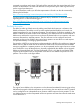
• The front panel LEDs and LAN LEDs of the server blade change color and blink to help identify
specific issues, and display LAN activity.
For information on LED locations and states, see “Front panel LEDs” (page 86).
• The SEL provides detailed information about the errors identified by the LEDs.
For server alerts of levels 3-5, the attention condition on the server LED can only be cleared by
cycling DC power.
If the LEDs and SEL do not give you enough information for you to identify the issue you are
experiencing, HP also provides diagnostic tools with each operating system (see “Troubleshooting
tools” (page 84) for more details).
NOTE: Always examine the iLO 3 MP SEL in the case of a blinking yellow or red front panel
health LED, before replacing any hardware.
Executing recommended troubleshooting methodology
The recommended methodology for troubleshooting a server blade error or fault is as follows:
1. Consult the system console for any messages, emails, and so on, pertaining to a server blade
error or fault.
2. View the front panel LEDs (power and health), locally or remotely through the iLO 3 MP vfp
command.
3. Read the symptom/condition information in the left column of Table 9 (page 81).
4. Perform the actions specified in the Action column.
For more details, see the appropriate subsection of this chapter, where this information is provided
in the Action column. The Action you are directed to perform might be to access and read one or
more error logs (the event log and/or the FPL).
You can follow the recommended troubleshooting methodology, and use Table 9 and Table 10
(page 83) or go directly to the subsection of this chapter which corresponds to your own entry
point. Table 8 provides the corresponding subsection or location title for these different entry points
(for example, to start by examining the logs, go directly to “Errors and error logs” (page 93)).
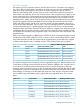
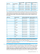
Table 8 Troubleshooting Entry Points
Subsection or LocationEntry Point
See “Basic and advanced troubleshooting tables” (page 81) , “Troubleshooting
tools” (page 84), and “Front panel LEDs” (page 86).
Front panel LEDs
See “Virtual Front Panel LEDs in the iLO 3 TUI” (page 89)Virtual Front Panel LEDs in the iLO
3 TUI
See “Errors and error logs” (page 93).SEL and
FPLs
See “Troubleshooting tools” (page 84).Offline and Online Diagnostics
See http://www.compaq.com/support/svctools/webes/ for more information
about this tool).
System Event Analyzer
80 Troubleshooting