
User's Manual
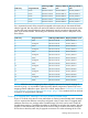
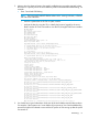

Mapping to BL870c i4 portsVCM assigned WWNAssigned SANProfile entry
Auxiliary MEZZ1:2-b50:06:0B:00:00:C3:26:1Eunassigned8
Monarch LOM:3-b50:06:0B:00:00:C3:26:20SAN-59
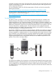
The Monarch blade LOM3 now has the correct SAN assignment so the HW path from the original
server has been restored, but the WWN is changed so a change to the SAN infrastructure may
be necessary so that the required storage devices associate with the new WWN. Also note that
this enables FCoE on port 'b' of the Auxiliary blade LOM and MEZZ FlexFabric devices leaving
only three ports on each device available for Ethernet connections. LOM3 and LOM4 belong to
the same physical LOM device on the blade so because both 'b' ports on a LOM device must be
configured with the same protocol, the Monarch LOM:4-b will be enabled as an FCoE port and
not available as an Ethernet port since LOM:3-b has an FCoE entry mapped to it. The Auxiliary
blade LOM3 and LOM4 'b' ports, however, remain available as Ethernet ports because neither
of those ports have an FCoE connection entry mapped to them.
Ethernet network connections
The Ethernet connection entries in a profile are handled differently from SAN entries in order to
balance the use of Flex-10 ports (even if no Flex-10 ports are used, the same balanced approach
is used). Virtual Connect manager distributes the Ethernet connection entries across all of the blades
in a server, and on each blade it distributes connection entries across all of the Ethernet physical
ports. This is done so that as few Flex-10 sub-ports are used as needed, which results in maximum
band-width available to each Flex-10 sub-port. This distribution of Ethernet connection entries across
all Ethernet ports is done for single-blade servers, too. The net result is that the mapping of Ethernet
connection entries in a profile assigned to a server will likely change when that server is upgraded.
Consider the following examples.
• • If the upgrade is from a BL860c i4 to a BL870c i4 then every other Ethernet connection
entry starting with the first entry (for example, the first, third, fifth, etc. entries) will be mapped
to ports on the Monarch blade, and every other entry starting with the second entry (for
example, the second, fourth, sixth, etc. entries) will be mapped to ports on the Auxiliary blade.
• If the upgrade is from a BL860c i4 to a BL890c i4, then every fourth Ethernet connection entry
starting with the first entry (for example, the first, fifth, ninth, etc. entries) will be mapped to
ports on the Monarch blade; every fourth entry starting with the second entry (for example,
the second, sixth, tenth, etc. entries) will be mapped to the first Auxiliary blade; every fourth
entry starting with the third entry (for example, the third, seventh, eleventh, etc. entries) will
be mapped to the second Auxiliary blade; and finally every fourth entry starting with the fourth
entry will be mapped to ports on the 3rd Auxiliary blade.
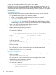
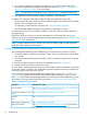
As an example, consider a profile with 8 Ethernet connection entries where each entry defines a
connection to a different network (this makes it easy to see what happens when an upgrade is
done). Assume that the profile is assigned to a BL860c i4 that is upgraded to a BL870c i4. Assume
that VC Flex-10 Interconnect modules exist in bays 1 and 2, thus the FlexFabric LOM ports on the
blades are utilized as Flex-10 ports. The following table shows how these entries are mapped to
ports on the original server and to the blades in the upgraded server. The examples here assume
that the LOM FlexFabric devices are not in FCoE mode. That is, there are no FCoE connection
entries in the VCM server profile.
Mapping to BL870c i4
ports
Mapping to BL860c i4
ports
VCM assigned MAC
addressAssigned networkProfile entry
Monarch LOM1–aMonarch LOM1–a00-17-A4-77-90-10LAN-11
Auxiliary LOM1–aMonarch LOM2–a00-17-A4-77-90-12LAN-22
Monarch LOM2–aMonarch LOM3–a00-17-A4-77-90-14LAN-33
74 Optional components