HP Integrity BL860c i4, BL870c i4 & BL890c i4 Server Blade User Service Guide Abstract This document contains specific information that is intended for users of this HP product.
© Copyright 2012, 2013 Hewlett-Packard Development Company, L.P. The information contained herein is subject to change without notice. The only warranties for HP products and services are set forth in the express warranty statements accompanying such products and services. Nothing herein should be construed as constituting an additional warranty. HP shall not be liable for technical or editorial errors or omissions contained herein.
Contents 1 Overview..................................................................................................7 Server blade overview...............................................................................................................7 Server blade components..........................................................................................................8 2 Site preparation.........................................................................................
Booting HP-UX in single-user mode.......................................................................................34 Booting HP-UX in LVM-maintenance mode.............................................................................34 Shutting down HP-UX..........................................................................................................34 5 Optional components................................................................................36 Partner blades.........................
SAS hard drive LED combinations...............................................................................87 Blade Link LEDs.............................................................................................................89 Virtual Front Panel LEDs in the iLO 3 TUI................................................................................89 SUV Cable and Ports..........................................................................................................
New and changed information in this edition...........................................................................120 Typographic conventions.......................................................................................................120 Standard terms, abbreviations, and acronyms...............................................122 A RAID configuration and other utilities........................................................125 Configuring a Smart Array Controller.............................
1 Overview The HP Integrity BL860c i4 Server Blade is a dense, low-cost, Intel® Itanium® processor server blade. Using a Blade Link hardware assembly, multiple BL860c i4 Server Blades can be conjoined to create dual-blade, four socket and quad-blade, eight socket variants.
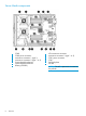
Server blade components 1 2 3 4 5 6 7 8 Overview CPU0 CPU0 power connector Mezzanine connector 1 (type 1) Mezzanine connector 2 (type 1 or 2) System board thumbscrew System board thumbscrew Battery (CR2032) 8 9 10 11 12 13 ICH mezzanine connector Mezzanine connector 3 (type 1 or 2) CPU1 power connector CPU1 SAS backplane Pull tab NOTE: The iLO 3 password is located on the pull tab.
2 Site preparation The HP Integrity BL860c i4 Server Blade does not have cooling or power systems. Cooling and power is provided by the c-Class enclosure. IMPORTANT: To avoid hardware damage, allow the thermal mass of the product to equalize to the temperature and humidity of the installation facility after removing the shipping materials.
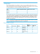
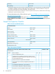
Operating 20% to 80% Non-operating 5% to 95% 1 2 All temperature ratings shown are for sea level. An altitude derating of 1°C per 304.8 m (1.8°F per 1000 ft) to 3048 m (10,000 ft) is applicable. No direct sunlight allowed. Upper operating limit is 3,048 m (10,000 ft) or 70 Kpa/10.1 psia. Upper non-operating limit is 9,144 m (30,000 ft) or 30.3 KPa/4.4 psia. Storage maximum humidity of 95% is based on a maximum temperature of 45°C (113°F).
Table 4 Site Inspection Checklist (continued) Check either Yes or No. If No, include comment number or date. 8. Is a network line available? 9. Is a telephone line available? 10. Are customer-supplied peripheral cables and LAN cables available and of the proper type? 11. Are floor tiles in good condition and properly braced? 12. Is floor tile underside shiny or painted? If painted, judge the need for particulate test. Comment or Date Power and Lighting Number Area or Condition 13.
Table 4 Site Inspection Checklist (continued) Check either Yes or No. If No, include comment number or date. Number Area or Condition 31. Are cabinets available for tape and disc media? 32. Is shelving available for documentation? Comment or Date Yes No Training Number Area or Condition 33. Are personnel enrolled in the System Administrator’s Course? 34. Is on-site training required? Power subsystem The power subsystem is located on the system board.
Verifying site preparation Verifying site preparation is an essential factor of a successful server blade installation, and includes the following tasks: • Gather LAN information. Determine the two IP addresses for the iLO 3 MP LAN and the server blade LAN. • Establish a method to connect to the server blade console. For more information on console connection methods, see “Using iLO 3” (page 25) for more information. • Verify electrical requirements.
3 Installing the server blade into the enclosure Installation sequence and checklist Step Description 1 Perform site preparation (see “Site preparation” (page 9)for more information). 2 Unpack and inspect the server shipping container and then inventory the contents using the packing slip. 3 Install additional components shipped with the server. For these procedures, see the documentation that with the component or the user service guide. 4 Install and power on the server blade.
2. Remove the three adjacent blanks. Removing a c7000 device bay divider 1. Slide the device bay shelf locking tab to the left to open it. 2. Push the device bay shelf back until it stops, lift the right side slightly to disengage the two tabs from the divider wall, and then rotate the right edge downward (clockwise).
3. Lift the left side of the device bay shelf to disengage the three tabs from the divider wall, and then remove it from the enclosure. Removing a c3000 device bay mini-divider or device bay divider 1. 16 Slide the locking tab down.
2. Remove the mini-divider or divider: • c3000 mini-divider: Push the divider toward the back of the enclosure until the divider drops out of the enclosure. • a. b. c. d. c3000 divider Push the divider toward the back of the enclosure until it stops. Slide the divider to the left to disengage the tabs from the wall. Rotate the divider clockwise. Remove the divider from the enclosure.
Interconnect bay numbering and device mapping • HP BladeSystem c7000 Enclosure • HP BladeSystem c3000 Enclosure To support network connections for specific signals, install an interconnect module in the bay corresponding to the embedded NIC or mezzanine signals.
Server blade signal c7000 interconnect bay c3000 interconnect bay Mezzanine 2 5 and 6 3 and 4 7 and 8 3 and 4 5 and 6 3 and 4 7 and 8 3 and 4 Mezzanine 3 Interconnect bay labels For detailed port mapping information, see the HP BladeSystem enclosure installation poster or the HP BladeSystem enclosure setup and installation guide for your product on the HP website (http://www.hp.com/go/bladesystem/documentation).
3. Install the server blade. The server blade should come up to standby power. The server blade is at standby power if the blade power LED is amber. Server blade power states The server blade has three power states: standby power, full power, and off. Install the server blade into the enclosure to achieve the standby power state. Server blades are set to power on to standby power when installed in a server blade enclosure. Verify the power state by viewing the LEDs on the front panel, and using Table 5.
Powering on the server blade Use one of the following methods to power on the server blade: NOTE: To power on blades in a conjoined configuration, only power on the Monarch blade. See “ Blade Link bay location rules” for rules on the definition of the Monarch blade. • Use a virtual power button selection through iLO 3. • Press and release the Monarch power button. When the server blade goes from the standby mode to the full power mode, the blade power LED changes from amber to green.
NOTE: Before installing the Blade Link for BL870c i4 or BL890c i4, make sure the following statements are true: • All blades have the same CPU SKUs • All blades have the same hardware revision (only use BL860c i4, BL870c i4, or BL890c i4 Server Blades) • All blades have CPU0 installed • All blades have the same firmware revision set • All blades follow the memory loading rules for your configuration, see “DIMMs” (page 44) • The enclosure OA firmware is compatible with the blade firmware • The M
Number of conjoined blades Class BL2E BL4 1 Supported enclosures Partner blade Blade location rules support? c3000 Bays 1&2, 3&4 with Monarch blade in odd bay Partner blade half-height bay number / Server blade full-height bay number 2 (BL870c i4) c7000 only Bays 2&3, 4&5 or 6&7 with Monarch blade in even bay using full-height numbering Yes Bottom half-height bay 9 paired with full-height bays 2&3, bottom half-height bay 11 paired with full-height bays 4&5, bottom half-height bay 13 paired with
8. 9. Pull the handle all the way out Align the guide pins on the back of the Blade Link to the holes on the front of the server blades. As you insert the pins into the holes, ensure the face on the Blade Link is evenly aligned parallel to the face of the server blades. 10. Press firmly on the left and right sides of the Blade Link face until the handle naturally starts to close. CAUTION: If not properly aligned, you can damage the Blade Link 11. Close the handle when it has engaged. 12.
15. Still in the iLO 3 Command Menu, power on the Monarch blade with the PC -on -nc command. Powering on the Monarch blade will power the entire conjoined system on. 16. Boot the Monarch blade. Booting the Monarch blade boots the entire conjoined system. Using iLO 3 The iLO 3 subsystem is a standard component of selected server blades that monitors blade health and provides remote server manageability.
NOTE: 4. If no option is selected, normal boot will proceed after ten seconds. Depending on how the server blade was configured from the factory, and if the OS is installed at the time of purchase, you are taken to: • UEFI shell prompt • OS login prompt If the server blade has a factory-installed OS, you can interrupt the boot process to configure your specific UEFI parameters. If you are at the UEFI shell prompt, go to “UEFI Front Page” (page 26).
To configure specific devices, press D or d to launch the Device Manager. This is an advanced feature and should only be performed when directed. To perform maintenance on the system such as adding, deleting, or reordering boot options, press M or m to launch the Boot Maintenance Manager.
To perform more advanced operations, press S or s to launch the UEFI Shell. To view the iLO 3 LAN configuration, press I or i to launch the iLO 3 Setup Tool. Saving UEFI configuration settings There are other UEFI settings you can configure at this time. For more UEFI configuration options, see Appendix A (page 125).
Installing the latest firmware using HP Smart Update Manager The HP Smart Update Manager utility enables you to deploy firmware components from either an easy-to-use interface or a command line. It has an integrated hardware discovery engine that discovers the installed hardware and the current versions of firmware in use on target servers. This prevents extraneous network traffic by only sending the required components to the target.
4 Operating system procedures Operating systems supported on the server blade • HP-UX 11i v3 HWE 1209 Installing the operating system onto the server blade The following procedures describe generalized operating system installation. For more details, see the operating system documentation. Installing the OS from an external USB DVD device or tape device NOTE: Tapeboot requires BL8x0c i4 system firmware bundle 42.
5. Locate the device you want to boot from. a. For USB DVD, locate the device: i. Use the map command to list all device names from the UEFI Shell prompt. The map command displays the following: fs2:\> map Device mapping table fs6 :Removable CDRom - Alias cd66d0a blk6 PcieRoot(0x30304352)/Pci(0x1D,0x7)/USB(0x3,0x0)/CDROM(0x0) From the list generated by the map command, locate the device name (in this example, fs6) NOTE: Your DVD drive might not be named fs6.
For more information regarding loading the OS with vMedia, see the vMedia Chapter of the HP Integrity Integrated Lights-Out Management Processor Operations Guide. NOTE: After the OS is loaded, make sure to save your nonvolatile memory settings to preserve boot entries in case of blade failure. Configuring system boot options • Boot Manager Contains the list of boot options available. Ordinarily the boot options list includes the UEFI Internal Shell and one or more operating system loaders.
1. Access the UEFI Shell environment. a. Log in to iLO 3 for Integrity and enter the CO command to access the system console. When accessing the console, confirm that you are at the UEFI Front Page. If you are at another UEFI menu, then choose the Exit option or press X or x to exit the menu. Exit until you return to the screen that lists the keys that can be pressed to launch various Managers. b. 2. Press S or s to launch the UEFI shell.
7. 8. Exit the console and iLO 3 MP interfaces. Press Ctrl–B to exit the system console and return to the MP Main Menu. To exit the MP Main Menu, press X or x. Booting HP-UX from the UEFI Shell 1. 2. 3. 4. 5. Access the UEFI Shell. From the UEFI Front Page, press S or s to launch the UEFI shell. Use the map command to list the file systems (fs0, fs1, and so on) that are known and have been mapped. To select a file system to use, enter its mapped name followed by a colon (:).
2. Issue the shutdown command with the appropriate command-line options. The command-line options you specify determines the way in which HP-UX shuts down and whether the server is rebooted. Use the following list to choose an HP-UX shutdown option for your server: • Shut down HP-UX and halt (power off) the server using the shutdown -h command. Reboot a halted server by powering on the server using the PC command at the iLO 3 MP Command menu.
5 Optional components If your server blade has no additional components to install, go to “Installing and powering on the server blade” (page 14). Partner blades The following partner blades are supported: • Ultrium 448c Tape Blade • SB920c Tape Blade • SB1760c Tape Blade • SB3000c Tape Blade • SB40c Storage Blade • D2200sb Storage Blade IMPORTANT: In c7000 enclosures, partner blades are supported with BL860c i2 servers and BL870c i2 servers with BL2E blade links.
Hot-plug SAS disk drives The server blade supports up to two hot-plug SAS drives. CAUTION: To prevent improper cooling and thermal damage, do not operate the server blade or the enclosure unless all hard drive and device bays are populated with either a component or a blank. IMPORTANT: The disk drive does not seat properly when 180° out of alignment. Verify the orientation before insertion. NOTE: For a list of supported disk drives for the server blade, see: “Server blade components list” (page 99). 1.
4. Close the lever to lock the drive into place. Installing internal components Removing the access panel 1. 2. 3. Lift the access panel latch. Slide the access panel backwards approximately 2 cm (0.75 in). Remove the access panel by lifting it straight up and off the server blade. After the access panel is off, you can do the following: 38 • Add an additional processor (“Processor and heatsink module”). • Add additional memory DIMMs (“DIMMs”).
Processor and heatsink module Processor load order Observe the following guidelines when installing additional processors: • In a BL860c i4, CPU0 is installed before CPU1. • In a BL870c i4 or BL890c i4, each blade must have CPU0 installed. • When adding additional CPUs in a conjoined configuration: ◦ Load both CPU0 and CPU1 in the Monarch blade first ◦ Load additional CPUs in sequence, from lowest slot-numbered blade to highest. CAUTION: The pins on the processor socket are very fragile.
2. Transfer the duplicate part/serial numbers label from the processor module to the processor heatsink. a. Remove the duplicate tear-away label that lists the part and serial numbers from the processor module. b. Place the label on the top of the heatsink. 3. Install the processor over the load posts. NOTE: Ensure pin 1, indicated on the empty socket with an embossed triangle, matches the pin 1 marker on the processor module, the chamfered corner of its attached voltage regulator heatsink. 4.
CAUTION: During installation, after removing the protective cover from the heatsink: • Do not touch or come into contact with the thermal interface material. • Immediately install the heatsink. CAUTION: To avoid damage to the server blade and processor, ensure the processor heatsink locking handle is fully back against the stops, rotated about 120° back. Also verify that the plastic tabs on the processor heatsink are pulled fully out before installation. 5. Install the heatsink over the load posts.
CAUTION: To prevent thermal instability and damage to the server blade, do not separate the processor module from the processor's heatsink after they have been coupled.
6. Secure the heatsink to the processor a. Slide both plastic locking tabs into place. (See callout 1 in the following figure). b. Grasp and rotate the latch downward. (See callout 2 in the following figure.) WARNING! The heatsink locking lever can constitute a pinch hazard, keep your hands on top of the lever during installation to avoid personal injury. NOTE: Positive engagement clicking should occur during mating of the processor heat sink and processor module onto the socket to ensure proper seating.
IMPORTANT: If you are adding an additional processor to your server blade, the DIMMs in the server blade must be reconfigured to support both CPUs. For more information, see “DIMM pair load order” (page 45). DIMMs DIMM installation guidelines Observe the following guidelines when installing memory: • Use only HP low-profile (1.2 in.) DIMMs. IMPORTANT: DIMMs from other sources may adversely affect data integrity. • In a BL860c i4 Server Blade, memory is loaded in identical pairs.
Performance The maximum number of usable DIMM slots, and therefore the maximum amount of memory for any particular configuration is tied to the number of processors used in the configuration. In addition, the conjoined blade products all have minimum processor recommendations (oner per conjoined blade) for best performance. There are 12 DIMMs associated with each processor. Each processor has DIMM pairs A through F. A processor must installed to access its associated memory.
Figure 2 Mixed DIMM load order Table 6 DIMM pair load order CPU0 CPU1 1st 3A 4A — — 2nd 9B 10B — — 3rd 1C 6C — — 4th 7D 12D — — 5th 2E 5E — — 6th 8F 11F — — 1st 3A 4A — — 2nd — — 1A 7A 3rd 9B 10B — — 4th — — 6B 10B 5th 1C 6C — — 6th — — 3C 9C 7th 7D 12D — — 8th — — 4D 12D 9th 2E 5E — — 10th — — 2E 8E 11th 8F 11F — — 12th — — 5F 11F CPU0 only Both CPUs loaded 46 Optional components
DIMM quad load order rules Figure 3 DIMM quad load order Figure 4 Mixed DIMM load order Table 7 DIMM quad load order CPU0 Both CPUs loaded CPU1 1st 3A 4A 9B 10B — — — — 2nd — — — — 1A 7A 6B 10B 3rd 1C 6C 7D 12D — — — — 4th — — — — 3C 9C 4D 12D 5th 2E 5E 8F 11F — — — — 6th — — — — 2E 8E 5F 11F Installing internal components 47
NOTE: • If more than two DIMM types are installed in the BL870c i4 or BL890c i4 systems, the customer will receive a warning indicating that optimum interleaving is not possible and memory may be de-allocated. Mixing more than two DIMM types is only supported on the BL860c i4. • If DIMMs are loaded in pairs in the BL870c i4 or BL890c i4 systems, the customer will receive a warning indicating that the memory is not configured according to the HP loading rules and some memory may be de-allocated.
8. Align the DIMM's notch with the slot's notch. CAUTION: Use only HP low profile DIMMs. DIMMs from other sources might adversely affect data integrity. DIMMs do not seat fully if turned the wrong way. DIMMs in a pair or quad must be identical. 9. Insert a DIMM in a slot and push down firmly until the latches click shut, first one latch and then the other. IMPORTANT: To ensure proper function of the memory baffle, all DIMM latched must be in the CLOSED position.
4. 5. Align the mezzanine connector on the option card with the mezzanine connector on the system board. Press down on the connector to seat the card. CAUTION: To prevent damage to the server blade, apply pressure over the mezzanine connector when installing the mezzanine card. Do not apply pressure to the edges of the card. HP Smart Array P711m Controller The HP Smart Array P711m is a PCIe card supporting direct attach and shared SAS Storage.
Supercap pack mounting kit The HP Smart Array P711m Controller includes a cabled Supercap Pack which mounts inside the server using the orderable AM341A Mounting Kit for Low profile battery (HP part number AD399-2132A KIT, RAID BATTERY HOLDER). This kit contains a black metal mounting bracket and a mezzanine card blank. The mounting bracket clips onto a mezzanine card in slot 1. If no card is used in slot 1, the mezzanine card blank included in the kit must be installed to mount the bracket.
6. 7. Press the bracket thumbscrew clip over the thumbscrew closest to the mezzanine post. Push the remaining bracket foot over the other edge of the mezzanine card or mezzanine card blank. CAUTION: Push only enough to anchor the bracket, keeping the bracket level. CAUTION: To avoid damage to the power cable ensure the battery bracket does not pinch the power cable to the power connectors. 8. Replace any mezzanine cards that you had to remove from mezzanine slot 2 (“Mezzanine cards” (page 115)).
NOTE: When a mixed configuration of BL860c i4, BL870c i4, and BL890c i4 server blades and other c-Class server blades are in the same enclosure, the preferred location for the P711m cards is slot 3. Use the procedure for installing standard mezzanine cards to install the SAS controller board, see “Mezzanine cards” (page 49) for more information. Installing the Supercap Pack The Supercap Pack snaps onto the mounting bracket to secure the Supercap Pack inside the server blade.
To remove the component, reverse the procedure. Replacing the access panel 1. 2. Place the access panel onto the server blade by lining up the keyways on the panel to the posts on the server blade chassis. Slide the access panel toward the front of the server blade until the panel lock button snaps into place. Upgrading a conjoined configuration This section contains information required to complete an upgrade of a BL860c i4, BL870c i4, or BL890c i4 server blade.
Upgrade kit contents • The HP Integrity BL860c i4, BL870c i4 & BL890c i4 Server Blade Upgrades Read Me First . • One of the following Upgrade Blade Links: ◦ AM395A HP BL8x0c i4 Upgrade BL2 Blade Link ◦ AM396A HP Integrity BL870c i4 Upgrade BL2-c7E Blade Link ◦ AM398A HP BL8x0c i4 Upgrade BL4 Blade Link NOTE: Each Blade Link will include a new Product Number label to attach to the system label carrier card; the actual part number will depend on the type of upgrade ordered.
Supported operating systems • HP-UX 11i v3 OE Update for September 2012 IMPORTANT: If you will be using HP-UX, review the HP-UX errata documentation that is listed at the following url: http://www.hp.com/go/Blades-docs Minimum firmware versions A minimum set of firmware is required for the blades and blade enclosures involved in the upgrade.
CO: VFP: CM: CL: SL: HE: X: Console Virtual Front Panel Command Menu Console Log Show Event Logs Main Help Menu Exit Connection [ilo002264fee2de] hpiLO-> cm (Use Ctrl-B to return to MP main menu.) [ilo002264fee2de] CM:hpiLO-> sr SYSREV Revisions Active Pending Bay 5 Bay 6 --------------------------------------------------------iLO FW : 01.41.01 01.41.01 01.41.01 System FW : 01.80 01.80 01.80 MHW FPGA : 02.00 02.00 02.00 Power Mon FW : 03.04 03.04 03.04 Front Panel HW : 04.00 04.00 04.00 PRS HW : 02.07 02.
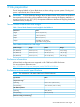
• OA CLI — Log in to the OA CLI through the serial console port or LAN and enter show oa info at the command prompt. OA8> show oa info Onboard Administrator #1 information: Product Name : BladeSystem c7000 Onboard Administrator with KVM Part Number : 456204-B21 Spare Part No.: 503826-001 Serial Number : OB12BP7320 UUID : 09OB12BP7320 Manufacturer : HP Firmware Ver. : 3.
VCM Use one of the following methods to determine the current VCM firmware version: • OA GUI — Select the Interconnect Bay 1 device and then select the Information tab. Under Information there is a Firmware Version line which indicates the current VC FW version installed on the primary VC interconnect module.
• VC Support Utility — Launch VC Support Utility – Interactive and enter version. ------------------------------------------------------------------------------HP BladeSystem c-Class Virtual Connect Support Utility Version 1.7.0 (Build 95) Build Date: Oct 13 2010 07:03:49 Copyright (C) 2007-2010 Hewlett-Packard Development Company, L.P.
processor of each blade (by enclosure bay number) can be chosen individually and the information displayed will include the information needed for comparison. For more information, see “Processor and heatsink module” (page 39), and “ CPU and heatsink module” (page 111). DIMM matching and loading rules The rules regarding DIMM load order change, especially when upgrading from a BL860c i4 to either a BL870c i4 or BL890c i4.
8. 9. If the enclosure uses Virtual Connect, then unassign any VC server profiles assigned to enclosure bays occupied by existing servers and any other enclosure bays which will be occupied by the upgraded server. See the HP Virtual Connect for c-Class BladeSystem User Guide for more information on VCM server profiles If this system is managed using HP Systems Insight Manager (HP SIM), then it's recommended that all nodes associated with the original servers be deleted now.
c. Place the product number portion from the Field Upgrade Only label on top of the old product number and barcode on the label carrier card from the Monarch Server. IMPORTANT: d. Do not cover the serial number on the label carrier card. Remove the position information label (the left hand label in the above picture) from the front of the upgrade Blade Link bezel. Temporarily remove the “Field Upgrade Only” label if it blocks the Blade Link trap door. e. f. 4.
10. Enter the sr command to view the system revision information. A sample output for a BL890c i4 is shown below. The BL890c i4 will show four blades composing the server blade, a BL870c i4 will show two. If the output does not show all of the blades expected, then there is a problem which must be resolved before proceeding. Reseating the Blade Link or individual blades may correct server blade conjoining problems.
NOTE: shown. This is just an example so actual version numbers may be different from what is If an update is required, it may need to be completed using the HPSUM Force Install option for both the iLO 3 and system firmware bundles. HPSUM should detect the mismatch and set the Force Install option by default. When finished, log back into the iLO 3 MP of the Monarch blade and enter sr from the Command Menu to verify that the firmware levels on all conjoined blades are now consistent and up to date. 12.
-> Command successful. d. After the iLO 3 MP reset (less than one minute), log back into the iLO 3 MP, go to the Command Menu, and enter sysset again to verify that the system information parameters have been set for correctly for both Primary and Secondary. The values between Primary and Secondary should now match.
nPartition : * A * B * C * D -> nPartition Configuration has been updated. -> iLO will now reset on all modified systems... Note: System environment variables may be cleared on all modified systems for the nPartition configuration to take effect. This configuration change may take several minutes to appear on other manageability user interfaces. -> iLO reset succeeded. -> Command successful. [ilo80c16e9877f4] CM:hpiLO-> 15.
17. 17. If the enclosure uses Virtual Connect, then the VCM server profiles for the partitions of the upgraded server should be assigned now. The Monarch Server VCM server profile should be assigned to the partition which includes the Monarch blade.
Booting the operating system The server blade has now been physically upgraded and it may be ready to boot to the OS. Certain upgrade scenarios require OS reinstallation: 1. Boot the OS. See “Operating system procedures” (page 30) for more information. IMPORTANT: A new Operating System license may be required for the upgraded server. See “Operating System Licenses” (page 70) for more information. 2. 3. 4. 5.
Blade link and system information parameters Every HP BL860c i4, BL870c i4 and BL890c i4 server blade has a set of information called the System Information Parameters which helps to identify the server blade and is used for certain applications and for the server blade warranty. This information includes: • product name • product number • UUID • serial number The System Information Parameters are stored in nonvolatile memory onboard the Blade Link and server blades.
contacted to get these new licenses. Full credit will be received when the original Monarch Server licenses are surrendered. The credit will reflect the current purchase price of the original licenses, not the original purchase price. For more information contact your HP sales representative. HP sales can also be contacted by following the link below: http://www.hp.com/large/contact/enterprise/index.html?key=1-57BVO&mcc=DRSR. The HP-UX license is delivered physically or electronically by certificate.
Possible changes due to VC profile mapping on the upgraded blade server Virtual Connect Manager supports assigning a VC server profile to each bladed server. Profiles can include VC-assigned: • UUID • serial number • Ethernet port MAC addresses with network assignments • FC HBA connection WWNs with FC SAN assignments.
FCoE SAN connections The mapping of FCoE connection entries is much the same as the FC connection entry mapping, but with a small twist. Each blade in the BL8x0c i4 family can have up to four embedded FCoE ports active which would appear in the VCM server profile mapping as LOM:1-b, LOM:2-b, LOM:3-b, and LOM:4-b. VCM will map FCoE connection entries from a profile to the Monarch blade LOM1 and LOM2 first, then to any FCoE mezzanine cards on the Monarch.
Profile entry Assigned SAN VCM assigned WWN Mapping to BL870c i4 ports 8 unassigned 50:06:0B:00:00:C3:26:1E Auxiliary MEZZ1:2-b 9 SAN-5 50:06:0B:00:00:C3:26:20 Monarch LOM:3-b The Monarch blade LOM3 now has the correct SAN assignment so the HW path from the original server has been restored, but the WWN is changed so a change to the SAN infrastructure may be necessary so that the required storage devices associate with the new WWN.
Profile entry Assigned network VCM assigned MAC address Mapping to BL860c i4 Mapping to BL870c i4 ports ports 4 LAN-4 00-17-A4-77-90-16 Monarch LOM4–a Auxiliary LOM2–a 5 LAN-5 00-17-A4-77-90-18 Monarch LOM1–b Monarch LOM3–a 6 LAN-6 00-17-A4-77-90-1A Monarch LOM2–b Auxiliary LOM3–a 7 LAN-7 00-17-A4-77-90-1C Monarch LOM3–b Monarch LOM4–a 8 LAN-8 00-17-A4-77-90-1E Monarch LOM4–b Auxiliary LOM4–a If it is important that each of the networks be mapped to the same ports on the Monarch
interconnect stacking links to allow all of the Monarch Server network connections to function correctly with no corrections needed in the original VC server profile. If you choose to use PI to assist the upgrade, there will be a pre-upgrade step to follow on the designated Monarch Server and then another step to follow after the upgrade. These two steps are detailed below but they must not be executed until they’re explicitly called for in the upgrade procedure steps.
gio_portable_image 3. (before) (now) 1 0 1 0 Immed The networking should be checked to make sure that the original system network instances function correctly. If the HP-UX boot reports a LAN interface configuration failure, then check the /etc/rc.log file for the failed instance number which may indicate something like the following example: ERROR: lan18 interface: ifconfig: no such interface "/sbin/rc2.
6 Troubleshooting This chapter provides strategies, procedures, and tools for troubleshooting server blade error and fault conditions. Methodology General troubleshooting methodology 1.
2. Narrow down the observed issue to the specific troubleshooting procedure required. Isolate the failure to a specific part of the server blade to perform more detailed troubleshooting. For example: • Issue - Front Panel LED blinking NOTE: The front panel health LED flashes amber with a warning indication, or flashes red with a fault indication. ◦ Look for a system alert on the OA or system console. ◦ Analyze the alert by using the SEL, to identify the last error logged by the server blade.
4. Your goal is to identify the failed FRU and replace it. You must now perform the specific removal and replacement procedure, and verification steps, see Chapter 7: “Removing and replacing components” (page 99) for more details. NOTE: 5. If multiple FRUs are identified as part of the solution, fix all identified failed FRUs. You might have to perform specific recovery procedures to finish the repair.
Basic and advanced troubleshooting tables Use the following troubleshooting tables to determine the symptoms or condition of a suspect server blade. The state of the front panel LEDs can be viewed locally.
Table 9 Basic Low End Troubleshooting (continued) Step Condition Action 4a Cannot see iLO 3 MP prompt on system console Nothing can be logged for this condition. The blade -- blade server power is on. iLO 3 MP heartbeat health LED state indicates that the server blade is either LED is flashing green. booting or running system FW, or booting or running OS. 1. Check the MP LAN connection. If the connection is functioning, check the serial console connectrion. 2.
Table 9 Basic Low End Troubleshooting (continued) Step Condition Action 6b “SBL_REMOVED “ - Blade Link was removed 1. If the Blade Link was not removed, be sure that is properly installed and fully seated. 2. Look for bent connector pins on the Blade Link. 6c “ILO_RST_REASON_SBL” - The iLO 3 was reset because the Blade Link was installed (FPL only) 1. Be sure that the Blade Link is properly installed and fully seated. 2. Look for bent connector pins on the Blade Link.
Table 10 Advanced Low End Troubleshooting (continued) Step Symptom/Condition Action 3. Use the following commands to obtain the system hardware status by capturing the logs. • sl -e -nc • l -f -nc • df -d • ps • ss • sr • sysset • npar • UEFI info all • VFP 4. Examine the iLO 3 MP logs for entries related to processors, processor power modules, shared memory, and core I/O devices (see “Errors and error logs” (page 93) for more details). This issue is fixed when the root cause is determined.
Controls and ports Front panel view 1 2 3 4 Monarch blade indicator UID LED Blade health LED NICs 1, 2, 3, 4 5 6 7 8 Monarch power button HDD bay 1 HDD bay 2 Blade power LED 9 10 11 Partition Identifier Physical Presence Button SUV connector Rear panel view 1 Power connectors 2 GBX signal connectors Server blade LEDs Troubleshooting tools 85
Front panel LEDs Item Description Status 1 Monarch blade indicator Green = Blade is acting as Monarch blade Off = Blade is not Monarch or is not conjoined 2 UID LED Blue = Identified Blue flashing = Active remote management Off = No active remote management 3 Blade health LED Green = Normal operation Amber flashing = Degraded condition Red flashing = Critical condition 4 NICs 1, 2, 3, 4 Green = Network linked Green flashing = Network activity Off = No link or activity 5 86 Troubleshooting
Item Description Status Amber = Blade is acting as Monarch and is in standby Off = Blade is not Monarch 6 SUV connector N/A 7 Physical Presence Button N/A 8 Partition Identifier Green = Blade is in a partition Off = Blade is not in a partition 9 Blade power LED Green = Server blade is powered on Amber = standby (auxiliary power available) 1 Off = Off 10 iLO 3 Heartbeat (behind grill) Green flashing = iLO 3 Active Amber flashing = iLO 3 failure Off = no standby voltage 1 If the Onboard Adm
Online/activity LED (green) Fault/UID LED (amber/blue) Interpretation On Off The drive is online, but it is not active currently. Flashing regularly (1 Hz) Amber, flashing regularly (1 Hz) Do not remove the drive. Removing a drive might terminate the current operation and cause data loss. The drive is part of an array that is undergoing capacity expansion or stripe migration, but a predictive failure alert has been received for this drive.
Blade Link LEDs Description Status Busy LED Green = Blade Link is currently active. Do not remove. Off = Blade Link is not currently active. Safe to remove. Virtual Front Panel LEDs in the iLO 3 TUI iLO 3 has no LED that equates to the Blade Health LED located on the front panel of each individual BL860c i4 Server Blade. The Blade Health LED represents the health of the individual server blade. The virtual LEDs in the iLO 3 GUI and TUI reflect system/partition health.
Table 11 Indications for the iLO 3 TUI LEDs (continued) NOTE: If the SYSTEM LED lights red, this counts as a FRU failure for the HEALTH LED. Flashing red Health of the partition is FATAL and the health of one or more blades within the partition are FATAL, meaning that: • A FRU has failed and A fatal event has been logged (Level seven events cause this indication if there are FRU failures on one of the blades in the partition.) A reset will clear this LED of a fatal event, but not a FRU failure.
SUV Cable and Ports The SUV port on the front of the server blade is used in conjunction with an SUV cable to connect the server to external devices such as a terminal emulator or monitor. In a conjoined server, only the SUV port on the Monarch Server is active. CAUTION: The SUV cable is not designed to be used as a permanent connection. Use caution when walking near the server blade when the SUV cable is installed. Hitting or bumping the cable might cause the port on the server blade to break.
Diagnostics A suite of offline and online support tools are available to enable troubleshooting server blade issues. In general, if the operating system (HP-UX) is already running, HP does not recommend shutting down the server blade. Use the online support tools. If the OS cannot be booted, use the offline support tools to resolve the issue. The offline support tools are available from the UEFI partition.
HP SMH is the application used to query information about monitored devices and view indications and instances on WBEM. This WBEM-based network management application enables you to create subscriptions and view indications. SysMgmtPlus functionality displays the property pages of various devices and firmware on HP SMH. SysMgmtPlus allows HP SMH to display improved property pages that contain dynamic content, providing the user to view and hide details of devices and firmware.
iLO 3 MP event logs The iLO 3 MP provides diagnostic and configuration capabilities. For more information on the iLO 3 MP commands, see the HP Integrity and HP 9000 Integrated Lights-Out Management Processor Operations Guide To access the MP: 1. Log in with the proper username and password. NOTE: the default login and password are: login = Administrator password = Randomly generated password found on the iLO 3 Network pull tab located on the right side of the Monarch blade.
2. 3. 4. 5. Enter cl to display the console history log. This log displays console history from oldest to newest. Enter Ctrl–B to return to the MP Main Menu. Enter sl to display the status logs. The status logs consist of: • System Event • Forward Progress • Current Boot • Previous Boot • Live Events • Clear SELs Enter Ctrl–B to return to the MP Main Menu. SEL review 1. 2. Access the iLO 3 MP command prompt. Run the sl command.
4. 5 ILO 1 2 4 ILO 1 2 3 ILO 1 2 2 ILO 1 2 Select a, then a threshold filter number to filter events to desired level. MP:SL Alert 1 2 3 5 7 Enter -> 5.
Identifying and troubleshooting firmware issues Erratic server blade operation, or unsuccessful boot to the UEFI Boot Manager or UEFI Shell, are symptoms of possible firmware issues. NOTE: Firmware issues are relatively rare. Look for other problem causes first. Probable firmware failure areas are: • Unsupported firmware installation • Corrupt firmware installation To troubleshoot firmware issues: 1.
Table 12 Server blade environmental specifications Parameter Operating Range Recommended Operating Range Temperature 5°C to 35°C (41°F to 20°C to 25°C (68°F 95°F) (up to 5000 feet) to 77°F) (up to 5000 feet) Maximum Rate of Change Non-Operating Range 10°C (50°F) / hr with tape 20°C (68°F) / hr without tape Relative Humidity 15-80% at 35°C (95°F) 40-60% at 35 degrees 30% per hour noncondensing 35°C (95°F) noncondensing noncondensing 98 Troubleshooting -40°C to 60°C (-40°F to 140°F) 90% at 65°C (149
7 Removing and replacing components Server blade components list NOTE: Part numbers are found by using the part nomenclature from this list to select the correct part from HP Partsurfer (http://www.partsurfer.hp.com/search.aspx). Table 13 CRU List Description with Part Number 8 Spare Part Number Memory DIMM,4GB PC3L-10600R,512Mx4,RoHS 708393-001 DIMM,8GB PC3L-10600R,512Mx4,RoHS 708394–001 DIMM,16GB PC3L-10600R,1Gx4,RoHS 708395–001 4 Processors Intel Itanium 9520 Four Core processor - 1.
Table 13 CRU List (continued) HP 300GB 10k SAS 2.5" HP DP HDD (part number 507127-B21) 507284-001 HP DP HDD HP 146GB 15k SAS 2.5" HP DP HDD (part number 512744-001 512547-B21) 450GB/10k 2.5" SAS 6Gb Hard Disk Drive (AM316A) (part number 581285-B21) 581310-001 600GB/10k 2.5" SAS 6Gb Hard Disk Drive (AM317A) 581311-001 HP 900GB 6G SAS 10K 2.5in DP E 619463-001 HP 300GB 6G SAS 15K 2.5in DP E (part number 627117-B21) 627195-001 HP 200GB SAS 2.
Table 13 CRU List (continued) BL2 (2 blades/CoP - now called Blade Link ) (part number AM377-60003) AM377-67003 BL4-M (4 blades/CoP) (part number AM377-60006) AM377-67006 BL4-S (4 blades/CoP) (part number AM377-60007) AM377-67007 BL2E-M (part number AM377-60010) AM377-67010 BL2E-S (part number AM377-60011) AM377-67011 Miscellaneous 3 BL8x0c i4 Base Unit (part number AM377-2001A) AM377-6901A 7 SAS disk backplane (part number AD399-60009) AD399-67009 10 System battery — 11 Smart Array batte
Preparing the server blade for servicing To service an internal server blade component, power off the server blade and remove it from the server blade enclosure. WARNING! Before proceeding with maintenance or service on a server blade that requires physical contact with electrical or electronic components, be sure that power is removed or safety precautions are followed to prevent electric shock and equipment damage. Observe all warning and caution labels on equipment.
5. Place a plastic protector over the connector on the back of the Blade Link and place it in an antistatic bag. NOTE: Plastic protectors are only provided with replacement Blade Links. Replacing the Blade Link for BL870c i4 or BL890c i4 configurations IMPORTANT: If you are installing the Blade Link for the first time, see “Installing the Blade Link for BL860c i4, BL870c i4 or BL890c i4 configurations” (page 21) for more information regarding bay location rules and other pre–installation requirements. 1.
12. In addition to the system information, the nPartition description information is stored on the Blade Link. To retain the partitioning configuration information, after replacing a BL you must run sysset to copy the system variables from the secondary to the primary, and reset iLO before powering back on. 13. Log into iLO 3 on the Monarch blade. For more information, see the HP Integrity iLO3 Operations Guide. 14.
5. Place a plastic protector over the connector on the back of the Blade Link and place it in an antistatic bag. NOTE: Plastic protectors are only provided with replacement Blade Links. IMPORTANT: If you are replacing a faulty Blade Link, take the label carrier card with the system ID values out of the faulty Blade Link and place it inside the label carrier door of the new Blade Link. To replace the component, reverse the removal procedure.
Server blade CAUTION: After you press the release button, the server blade is unlocked from the enclosure. Use both hands to support the server blade when you remove it from the rack. The server blade weighs approximately 9 kg (20 lb). CAUTION: The enclosure fans might still be running when the server blade is in standby mode. Opening the lever removes all power from the server blade. 1. 2. 3. Power off the server blade.
Disk drive blanks The server blade has two disk drive bays. If you only purchased one hard disk, then your server blade has a hard drive blank installed. Hard drive blanks maintain proper airflow throughout the server blade. CAUTION: Populate hard drive bays with a disk drive or a disk drive blank. Operating the server blade without a disk drive or disk drive blank causes improper airflow and cooling, which can lead to thermal damage.
For the location of the SAS disk LEDs, see “SAS disk drive LEDs” (page 87). To assess hard drive status, observe the SAS disk drive status LEDs. For an explanation of these LEDs, see “Front panel LEDs” (page 86). IMPORTANT: Before removing a SAS disk drive, perform a complete data backup. If disk drive mirroring is enabled, you do not have to power off the server blade before removing or replacing a SAS disk drive.
3. Pull the DIMM baffle straight up and out. To replace the component, reverse the removal procedure. DIMMs The memory subsystem supports only DDR3 SDRAM technology using industry-standard 1.2” high DIMMs. Single DIMM sizes BL860c i4 Min / Max BL870c i4 Min / Max Memory size Memory size BL890c i4 Min / Max Memory size 4 GB 8 GB / 96 GB 16 GB / 192 GB 32 GB / 384 GB 8 GB 16 GB / 192 GB 32 GB / 384 GB 32 GB / 768 GB 16 GB 32 GB / 384 GB 64 GB / 768 GB 64 GB / 1.
8. Remove the DIMM from the slot. IMPORTANT: DIMMs do not seat fully if turned the wrong way. To replace the component, reverse the removal procedure. IMPORTANT: (page 44)). Follow the DIMM installation guidelines when replacing or adding DIMMs (“DIMMs” CPU baffle CAUTION: To prevent damage to the server blade, never power on a server blade without a CPU baffle or CPU in each CPU socket. The CPU baffle is needed for proper system cooling CAUTION: Immediately install a CPU baffle in an empty CPU socket.
3. Pull the CPU baffle straight up and out. To replace the component, reverse the removal procedure. CPU and heatsink module The BL860c i4 Server Blade contains a processor subsystem accommodating one or two Intel Itanium processor modules.
2. 3. 4. Remove the access panel (“Access panel” (page 106)). Disconnect the power cord (see 1 below) Rotate the CPU locking handle up and back until it reaches a hard stop (see 2 below) WARNING! The heatsink locking lever can constitute a pinch hazard, keep your hands on top of the lever during installation to avoid personal injury. 112 5. Pull both plastic tabs out (see 3 below). 6. Lift the CPU and heatsink off of the socket, pulling straight up.
7. If the CPU is not being replaced, install a CPU baffle (“ CPU baffle” (page 110)). CAUTION: To avoid damage to CPU socket pins and ensure proper system cooling, install a CPU baffle in an empty CPU socket. The replacement CPU module is shipped from HP without a heatsink. You will need to order and attach a heatsink to the processor module before installing them for repair. See “Processor and heatsink module” (page 39) for more information on the installation procedure.
SAS backplane The SAS disk backplane supports two small form factor hard disk drives. The backplane supports hot-plugging a single SAS drive at a time. The activity LEDs and drive present LEDs are controlled by a preprogrammed system-on-chip. The system board hosts the SAS controller and supplies 12 V, 5 V, and 3.3 V standby power to the backplane. The SAS backplane is connected to the system board with a right angle connector.
2. 3. Remove the access panel (“Access panel” (page 106)). Remove the battery. To replace the component, reverse the removal procedure. Mezzanine cards The I/O subsystem is composed of embedded core I/O and up to three mezzanine cards. The server blade supports the following configurations: • Up to three type I mezzanine cards using up to x8-PCIe Gen-2 links • One type I and up to two type II mezzanine cards using up to x8-PCIe Gen-2 links The server blade does not support PCI Hot Plug. 1.
ICH mezzanine board The ICH mezzanine card houses the following components: • Intel ICH10 South Bridge • ATI/AMD RN50/ES1000 Video Controller • Embedded TPM 1.21 • The internal USB port — NOT SUPPORTED FOR USE One ICH mezzanine board is required per server blade in the BL860c i4. In the BL870c i4 and BL890c i4. 1. Power off the server and remove it from the enclosure (“Preparing the server blade for servicing”). 2. Remove the access panel (“Access panel” (page 106)). 3.
Before sending in the system board and server blade for replacement, remove the following components: • The processor and heatsink module (“ CPU and heatsink module” (page 111)) • The processor air baffle (“ CPU baffle” (page 110)) • The DIMMs (“DIMMs” (page 109)) • The DIMM baffle (“DIMM baffle” (page 108)) • The Smart Array Supercap Pack (“Installing the Supercap Pack” (page 53)) • The Mezzanine cards (“Mezzanine cards” (page 115)) • The ICH mezzanine board (“ ICH mezzanine board” (page 116))
2. Use the indent to pull the door open.
8 Support and other resources Contacting HP Before you contact HP Be sure to have the following information available before you call contact HP: • Technical support registration number (if applicable) • Product serial number • Product model name and number • Product identification number • Applicable error message • Add-on boards or hardware • Third-party hardware or software • Operating system type and revision level HP contact information For the name of the nearest HP authorized reseller
HP Insight Remote Support Software HP strongly recommends that you install HP Insight Remote Support software to complete the installation or upgrade of your product and to enable improved delivery of your HP Warranty, HP Care Pack Service or HP contractual support agreement.
WARNING A warning calls attention to important information that if not understood or followed will result in personal injury or nonrecoverable system issues. CAUTION A caution calls attention to important information that if not understood or followed will result in data loss, data corruption, or damage to hardware or software.
Standard terms, abbreviations, and acronyms A ASIC Application-specific integrated circuit Auxiliary Any blade in a conjoined server other than the lowest-numbered blade B BBRAM Battery-backed RAM BBWC Battery Backed Write Cache BCH Boot console handler C CE Customer engineer CEC Core electronics complex CMC Corrected machine check CPE Corrected platform errors CRU Customer replaceable unit CSR Control status registers D DDNS Dynamic domain name system DHCP Dynamic host configuratio
L LDAP Lightweight directory access protocol LVM Logical volume manager M Monarch Designates a single-blade server, or lowest-numbered blade in a conjoined server MP Management processor MPS Maximum payload size N NIC Network interface card NVRAM Non-Volatile RAM O OA Onboard Administrator ORCA Option Rom Configuration for Arrays P PA-RISC Precision Architecture, Reduced Instruction Set Computing PCA Printed circuit assembly PCI Peripheral component interface PCI-X Peripheral compon
TUI Text user interface U UART Universal asynchronous receiver-transmitter UEFI Unified Extensible Firmware Interface, replaces EFI.
A RAID configuration and other utilities Configuring a Smart Array Controller Using the saupdate command The saupdate command is used to query or change the mode of the Smart Array P410i and Smart Array P411 controllers to HBA or RAID. Querying or changing modes is not supported for other controllers. The following are the newly added commands to saupdate: • get_mode • set_mode get_mode This command displays the current mode of the controllers.
set_mode IMPORTANT: If you are using HBA mode, do not install any disk that has previously been a part of a RAID volume into the system. Use set_mode to change the mode of the controller. If the controller is already in the required mode the following message appears: The controller at is already in HBA|RAID mode Syntax saupdate set_mode [-f] can be any one of the strings listed in Table 14 (page 125).
IMPORTANT: NOTE: After changing the mode, perform a reconnect-r command at UEFI. Commands are not case-sensitive Updating the firmware using saupdate 1. 2. 3. 4. 5. Download the firmware image file into the system's UEFI partition. Boot the system to the UEFI Shell and change directories to the UEFI partition.
4. Find the SAS Host Bus Adapter’s Driver ID in the list, and make a note of the corresponding Ctrl ID. NOTE: If the drivers listing shows X under CFG and DIAG, the drive is in RAID mode and you can run drvcfg against it. If the drivers listing shows - under CFG and DIAG, the drive is in HBA mode. Configuring RAID volumes using the ORCA menu-driven interface NOTE: The function keys cannot be used in ORCA if you are using a serial console. Substitute ESC followed by the corresponding number key.
The ORCA main menu contains the following options: • Create Logical Drive • View Logical Drive • Delete Logical Drive NOTE: If you are configuring the HP Smart Array P700m/512 Controller or the HP StorageWorks SB40c storage blade (P400 controller), then you can enter ORCA from POST by pressing the F8 key when prompted. Creating a logical drive 1. At the ORCA main menu, select Create Logical Drive. 2.
6. 7. To save the configuration, press F8. To acknowledge that the configuration was saved and return to the ORCA Main Menu, press Enter. Deleting a logical drive WARNING! Back up all necessary data before deleting the logical drive. When you delete a logical drive, data on the drive is not preserved. 1. At the ORCA main menu, select Delete Logical Drive. 2. Select a logical drive to be deleted.
3. F3 to delete the logical drive. 4. To acknowledge that the configuration was saved and return to the ORCA Main Menu, press Enter. Useful UEFI command checks saupdate.efi list Use saupdate.efi list to list controller information such as the controller version. drivers Use drivers to find the driver version and DRV #.
pci–i Use pci–i to find vendor information. UEFI UEFI is an OS and platform-independent boot and preboot interface. UEFI resides between the OS and platform firmware, allowing the OS to boot without having details about the underlying hardware and firmware. UEFI supports boot devices, uses a flat memory model, and hides platform and firmware details from the OS. NOTE: Unified EFI Forum, Inc. defines the specification used to implement UEFI.
Table 15 UEFI Shell Commands (continued) UEFI Shell Command Definition cp Copies one or more files or directories to another location cpuconfig Deconfigure/Reconfigure processor sockets and threads date Displays or changes the current system date dblk Displays one or more blocks from a block device dbprofile Manage direct boot profiles default Set default values devices Displays the list of devices managed by UEFI drivers devtree Displays the UEFI Driver Model compliant device tree dh Dis
Table 15 UEFI Shell Commands (continued) 134 UEFI Shell Command Definition ls Displays a list of files and subdirectories in a directory map Displays or defines mappings memconfig Set/View memory configuration settings memmap Displays the memory map mkdir Creates one or more directories mm Displays or modifies MEM/MMIO/IO/PCI/PCIE address space mode Displays or changes the console output device mode mount Mounts a file system on a block device mv one or more files or directories to anot
Drive paths in UEFI Devices in the server blade are represented by device paths in the UEFI shell. Each internal SAS drive could be configured either as: • RAID mode • HBA (raw) mode NOTE: A SAS drive in RAID mode is identified by "Scsi" in the device path A SAS drive in HBA mode is identified by “SAS” in the device path. NOTE: Unlike parallel SCSI, you cannot correlate UEFI device paths to internal SAS disk drive bays with SAS regardless of RAID/HBA mode.
Boot Options the Boot Options menu contains the following options: • Add Boot Option • Delete Boot Option • Change Boot Order Add Boot Option Use this option to add items to the Boot Options list.
1. Select a boot device type. 2. Use the File Explorer menu to locate the correct boot device. NOTE: File Explorer will load with the appropriate devices for the selected boot device. Delete Boot Option Use this option to remove boot options from the Boot Options list. NOTE: This does not delete any files, applications or drivers from your server.
1. 2. Press spacebar to toggle the checkbox for each boot options that you want to delete. Select Commit Changes and Exit to save the new settings and return to the Boot Maintenance Manager. Change Boot Order Use this option to change the order of boot options. If the first boot option fails, the server tries booting the second, then the third, and so forth, until a boot option succeeds or until all options have failed.
Driver Options The Driver Options menu contains the following options: • Add Driver Option • Delete Driver Option • Change Driver Order Add Driver Option Use this option to add driver options. To add a driver option: 1. Select Add Driver Using File.
2. Use the File Explorer menu to locate the correct driver. Delete Driver Option Use this option to remove driver options. NOTE: This does not delete any files, applications or drivers from your server. To remove driver options: 1. Press spacebar to toggle the checkbox for each driver that you want to delete. 2. Select Commit Changes and Exit to save the new settings and return to the Boot Maintenance Manager. Change Driver Order Use this option to change the load order of driver options.
Primary or Secondary The console device can be marked as primary. Only one console device can be selected as primary. If the you set a console device as primary, then the rest of the console devices in the system becomes secondary (if NOT in Not Configured state). Enable or Disable You can disable an active console, either primary or secondary, or enable a “Not Configured” console device.
Boot From File Use this option to manually run a specific application or driver. NOTE: This option boots the selected application or driver one time only. When you exit the application, you return to this menu. 1. Select a boot device type. 2. Use the File Explorer menu to locate the correct driver or file. Set Boot Next Value Use this option to run the selected boot option immediately upon entering the main Boot Manager menu.
Set Time Out Value Use this option to set the amount of time the server pauses before attempting to launch the first item in the Boot Options list. Interrupting the timeout during the countdown stops the Boot Manager from loading any boot options automatically. If there is no countdown, boot options must be selected manually. To set the auto boot timeout value, in seconds, select Set Timeout Value and enter the desired value. Reset System Use this option to perform a system reset.
iLO 3 MP The iLO 3 MP is an independent support system for the server. It provides a way for you to connect to a server and perform administration or monitoring tasks for the server hardware. The iLO 3 MP controls power, reset, ToC capabilities, provides console access, displays and records system events, and displays detailed information about the various internal subsystems. The iLO 3 MP also provides a virtual front panel used to monitor server status and the state of front panel LEDs.
B Regulatory information For important safety, environmental, and regulatory information, see Safety and Compliance Information for Server, Storage, Power, Networking, and Rack Products, available at http:// www.hp.com/support/Safety-Compliance-EnterpriseProducts.
Index A access panel removing, 106 replacing, 54, 106 antistatic wrist strap, 12 autoboot, 32 B Blade Link, 117 installing, 21 LEDs, 89 removing, 102 replacing, 103 boot option add, 136 change boot order, 138 delete, 137 Set Boot Next Value, 142 boot option maintenance manager menu, 135 boot options list, 32 add HP-UX, 32 booting from file, 142 HP-UX (LVM maintenance mode), 34 HP-UX (UEFI boot manager), 33 HP-UX (UEFI Shell), 34 HP-UX in single-server mode, 34 UEFI boot manager, 132 C c-Class enclosure se
booting in LVM maintenance mode, 34 booting in single-user mode, 34 Fault Management, 92 shutting down, 34 standard boot, 33 HP-UX Ignite, 28 HPSUM see HP Smart Update Manager I I/O subsystem, 115 ICH Mezzanine board removing, 116 replacing, 116 iLO 3 MP, 144 accessing UEFI from, 25 event log, 94 inspecting the shipping container, 13 installation order processors, 96 installing Blade Link, 21 heatsink module, 39 operating system with Ignite-UX, 31 operating system with vMedia, 31 processor, 39 SAS backplan
SAS backplane removing, 114 replacing, 114 SAS disk drives LEDs, 87 mirroring, 108 removing, 108 slot locations, 107 saupdate, 125, 127 firmware updates, 127 get_mode, 125 set_mode, 126 server battery removing, 114 replacing, 114 server blade , 21 access panel, 38, 54 components, 8 dimensions, 9 enclosure interconnect mapping, 18 front view, 85 LEDs, 87 overview, 7 powering off, 102 powering on, 20, 21 rear panel connectors, 85 rear view, 85 removing access panel, 106 removing from enclosure, 106 replacing