HP NetServer E 800 User Guide HP Part Number D9394-90008 Printed June 2000
Notice The information contained in this document is subject to change without notice. Hewlett-Packard makes no warranty of any kind with regard to this material, including, but not limited to, the implied warranties of merchantability and fitness for a particular purpose. Hewlett-Packard shall not be liable for errors contained herein or for incidental or consequential damages in connection with the furnishing, performance, or use of this material.
Contents 1 Controls, Ports, and Indicators ........................................................................ 1 Introduction ................................................................................................... 1 Front Panel................................................................................................ 1 Additional Front Panel Controls and Indicators........................................... 2 Rear View....................................................................
Contents Introduction ................................................................................................. 35 Tested PCI Boards .................................................................................. 35 Tools Required ........................................................................................ 35 Accessory Board Installation Guidelines ...................................................... 36 IRQ Settings...................................................................
Contents Menu Bar ................................................................................................ 62 Using the Setup Screens ......................................................................... 63 Changing the System Date and Time....................................................... 64 Setting the HP NetServer’s Boot Passwords ............................................ 65 Remote Console Feature.............................................................................
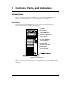
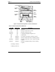
1 Controls, Ports, and Indicators Introduction Before operating the NetServer, familiarize yourself with the HP NetServer’s controls, ports, and indicators, as shown in Figures 1-1 through 1-3. Front Panel The front panel of the HP NetServer provides the controls and indicators commonly used when operating the NetServer. Flexible Disk Drive CD-ROM Drive Optional Back-Up Tape Drive Power ON/OFF/ Sleep Switch Power ON/ OFF/Sleep LED SCSI Drive Activity LED Figure 1-1.
Chapter 1 Controls, Ports and Indicators Table 1-1. Control Panel Switch and Indicators Control / Indicator Power On/Off/Sleep Switch Description This button turns the HP NetServer power On or Off, and if available, also transitions the NetServer between Power On and sleep states. If sleep states are not available, then this button only turns power On or Off.
Chapter 1 Controls, Ports, and Indicators Flexible Disk Drive Activity LED Eject Button CD-ROM Eject Button Activity LED Eject Button Status LEDs Backup Tape Drive (Optional) Figure 1-2. Input and Storage Device Controls and Indicators Table 1-2.
Chapter 1 Controls, Ports and Indicators NOTE For more information on the HP Tape Drive and its error codes, refer to the documentation provided with the tape drive or refer to Hewlett-Packard’s web site, at: http://www.hp.com Refer to Chapter 3, "Installing Mass Storage Devices," for installation information. Rear View The ports and connectors at the rear are listed below and shown in Figure 1-3.
Chapter 1 Controls, Ports, and Indicators Power Mouse Key Lock Keyboard USB(2) LAN Serial A Parallel Serial B External SCSI (Optional) Video SVGA Fold-Out Feet (4) Figure 1-3. Rear Panel and Ports Table 1-3. LAN Port (RJ45) LED Indicators Indicator Link LED Definition This green LED is the activity/link indicator. A steady on LED indicates a valid LAN link. A flashing LED indicates there is LAN activity. LAN Speed Indicator This yellow LED is the LAN speed indicator.
Chapter 1 Controls, Ports and Indicators Applying Power to the HP NetServer Powering-Up the NetServer NOTE Turn on power to the monitor connected to the HP NetServer before you power-on the NetServer. This allows proper auto-configuration of video output of the NetServer as it boots. 1. Ensure the HP NetServer’s power cord is connected to the power source. See Figure 1-3. 2. Press the Power button on the front control panel. See Figure 1-1.
Chapter 1 Controls, Ports, and Indicators Connecting AC Power to Multiple-Server Configurations The HP NetServer temporarily draws a large "inrush current," when first connected to an AC power source. This also occurs when the NetServer is in a standby mode (power is turned off, but the power cord is plugged into AC power). The inrush current is much greater than the NetServer’s normal operating current and generally, the AC power source can handle the normal inrush current.
Chapter 1 Controls, Ports and Indicators The NetServer supports certain types of system activity, which is used as wake-up events from these sleep states. These wake-up events can be generated from the power button, LAN activity, and scheduled events. NOTE The HP NetServer’s power management policies (transitions between various power states) and the user options are specific to the particular ACPI-compliant NOS installed on the NetServer.
2 Opening and Closing the HP NetServer Introduction This chapter describes how to remove and replace the HP NetServer’s main cover and adjust the stabilizing feet on the bottom of the chassis. WARNING Before removing the cover, always disconnect the power cord and unplug telephone cables. Disconnect the power cord to avoid exposure to high energy levels that may cause burns when parts are short-circuited by metal objects such as tools or jewelry.
Chapter 2 Opening and Closing the HP NetServer KeyLock Slotted Thumbscrews(3) Slotted Thumbscrews(3) Figure 2-1. Screws and Lock Holding on Cover 4. Remove the NetServer cover. See Figure 2-2. a. Place both hands into the slot handles at the rear of the cover on both sides. b. Pull the cover back to release it and then lift it up and off the chassis. Figure 2-2.
Chapter 2 Opening and Closing the HP NetServer 5. If you are installing accessories or servicing the NetServer, move the feet inward before turning it over on its right side. Refer to "Adjusting the HP NetServer Feet." The right and left sides are defined by facing the front of the HP NetServer. Replacing the Cover To replace the cover, follow these steps: 1. If you have been installing accessories or servicing the NetServer, return the feet to the normal position before turning the NetServer upright.
Chapter 2 Opening and Closing the HP NetServer 4. Push the cover forward using the slotted handles until it is seated in place. 5. Replace the six (6) T-15/slotted thumbscrews in the rear. See Figure 2-1. 6. Re-lock the cover with the key lock at the rear of the NetServer. Adjusting the NetServer Feet The stabilizing feet are used to steady the HP NetServer during normal operation and must be turned outward during normal use.
3 Installing Mass Storage Devices Introduction The HP NetServer E 800 comes standard with an IDE CD-ROM and a floppy disk drive with some configuration of SCSI hard disk drives and an optional SCSI tape backup drive. The internal mass storage cages can hold up to 5 SCSI hard drives (including a tape back-up drive) with cabling provided. Tools Required Check the mass storage device’s documentation for additional tool requirements.
Chapter 3 Installing Mass Storage Devices ◊ The IDE CD-ROM uses only one connector on the cable from the primary channel (IDE-1) connector. ◊ A secondary IDE connector (IDE-2) is available, but is not supported by Hewlett-Packard. • SCSI Device Selection ◊ Use only low-voltage differential (LVD) SCSI devices. ◊ Do not use high voltage differential (HVD) SCSI devices on either of the SCSI channels or damage will occur. ◊ Ensure the SCSI devices you install do not have terminations installed.
Chapter 3 Installing Mass Storage Devices Boot Priority The NetServer’s boot order should be considered when selecting a PCI slot on the system board. This is especially important if you are installing a board that requires an early number in the boot order. The board’s boot priority is set by its slot location in the boot order. By default the NetServer searches for boot devices in this order: 1. IDE CD-ROM drive 2. Flexible disk drive 3. Embedded SCSI A channel (typically the SCSI Drives) 4.
Chapter 3 Installing Mass Storage Devices Installed Mass Storage Devices Table 3-1 lists the number and types of mass storage devices that may be installed into the HP NetServer E 800. Table 3-1.
Chapter 3 Installing Mass Storage Devices Duplexing Hard Drives You may choose to duplex the drives in the HP NetServer’s removable hard disk drive cage (only four drives possible). The NetServer supports an option to duplex the drives using the embedded dual channel SCSI controllers (SCSI A and B). There must be at least two SCSI drives available in the hard disk drive cage to duplex the drives. The NetServer also supports HP’s NetRAID-1Si PCI Controller board to control the two duplexed channels.
Chapter 3 Installing Mass Storage Devices Latch Opening Shelf 1 Air Duct Latch Shelf 2 Shelf 3 Captive Screws (3) Shelves 4-7(4) Cable Clamp Channel B Channel A Figure 3-1. Moving the Air Duct CAUTION Install and remove connectors carefully, and avoid displacing any of the pins. 6. Unplug the power and SCSI cables to any hard disk drives already in the drive cage. If necessary, disconnect the SCSI cable from the cable clamp on the underside of the drive cage to free the drive cage. See Figure 3-1.
Chapter 3 Installing Mass Storage Devices Slots for Tabs Tabs(2) Captive Screws (3) First, insert screws through round holes in back (one each side). Figure 3-2. Adding a Hard Disk Drive CAUTION All mounting screws used to thread into the hard disk drive must be #6-32 and not exceed ¼-inch in length. Longer screws may cause internal damage to the mass storage device. Damage caused by incorrect mounting screws is not covered by the HP warranty. 10.
Chapter 3 Installing Mass Storage Devices If the round hole does not align with the mounting hole on the drive, use the nearest elongated hole. c. Repeat steps a-b on the other side of the cage. See Figures 3-2 and 3-3. 4th 3rd Tab 2nd HDD3 (Shelf 6) HDD4 (Shelf 7) Tab 1st Figure 3-3. Hard Disk Drive Cage Screw Holes 11. Reinstall the hard disk drive cage. Ensure the tabs at the front on the cage slide into the slots provided for each one. See Figures 3-2 and 3-3. 12.
Chapter 3 Installing Mass Storage Devices The power cable is split into two cables, each with three power connectors. The designed distribution is: ◊ One string of three: CD-ROM, optional tape drive, top hard disk drive. ◊ Second string of three: lower three hard disk drives. If a power connector has no mate (for example, no optional tape drive installed), leave it unconnected and use the connector designed for the device you are connecting. 14.
Chapter 3 Installing Mass Storage Devices Duplex Configuration SCSI Device 1 SCSI Device 2 SCSI Channel A SCSI Channel B* *Requires P1773A SCSI Cable Kit Figure 3-4. Duplexing Cable Configuration Tape Drive SCSI Device 1 SCSI Device 2 SCSI Device 3 SCSI Device 4 SCSI Channel A SCSI Channel B* *Requires P1773A SCSI Cable Kit Figure 3-5.
Chapter 3 Installing Mass Storage Devices Terminator SCSI Connectors (2) SCSI B Connector Figure 3-6.
Chapter 3 Installing Mass Storage Devices Installing the Optional Internal/External SCSI Cable Kit The HP NetServer E 800 can be configured to extend one of its SCSI channels (typically channel B) to an external SCSI connector. This allows you to connect additional external mass storage devices to the second channel of the NetServer’s embedded SCSI controller. It requires a second SCSI cable, HP NetServer E 800 Internal/External SCSI Cable Kit, PN: P1774A.
Chapter 3 2. Installing Mass Storage Devices Using a flat blade screwdriver, pop out the external SCSI knock-out at the connector location shown on the rear of the NetServer. See Figure 3-8. Figure 3-8. Connecting the Cable to the Rear of the NetServer 3. Thread the cable from the SCSI channel B connector, along the bottom edge of the chassis toward the rear of the chassis. See Figure 3-9. 4.
Chapter 3 Installing Mass Storage Devices External SCSI Connection SCSI B Connector Figure 3-9.
4 Installing Additional Memory Introduction The HP NetServer’s main memory is implemented using four memory slots on the system board and it supports up to 2 GB (512 MB x 4) of memory. The NetServer uses only 3.3V, 168-pin, 133 MHz, buffered, SDRAM DIMMs and ships with at least one 128 MB DIMM. The embedded video controller is provided with 4 MB standard video memory and cannot be upgraded. NOTE Use only PC 133 (133 MHz) SDRAM DIMMs acquired from Hewlett-Packard.
Chapter 4 Installing Additional Memory • Supported memory capacity ranges from 128 MB to 2 GB maximum (512 MB per DIMM slot x 4 DIMM slots total). The minimum capacity is 128 MB (one DIMM). • DIMM sizes may be mixed on the system board and may be loaded in any order (0 through 3). However, HP recommends starting at slot 0 and filling the slots in order with the largest size first: 0, 1, 2, and 3. • Open slots between DIMMs are permitted.
Chapter 4 Installing Additional Memory Latch Opening Air Duct Latch Figure 4-1. Opening the Air Duct CAUTION The memory modules are sensitive to static electricity and can be easily damaged by improper handling. Do the following when handling the accessory kit: Leave the memory module in the anti-static container until you are ready to install it. Always use an anti-static wrist strap and a grounding mat.
Chapter 4 Installing Additional Memory 6. Locate the DIMM slots. See Figure 4-2. DIMM Slots 0 1 2 3 System Board (Top View) Figure 4-2. DIMM Locations on System Board 7. Remove a DIMM from its container, handling the module by its edges. Lay it on an anti-static surface. 8. Choose a slot into which you want to install a DIMM. DIMMs may be installed in any combination, in any slot. CAUTION 30 Use only HP PC133 (133 MHz) buffered SDRAM DIMMs.
Chapter 4 Installing Additional Memory 9. Spread the two retaining latches on the slot outward. See Figure 4-3. 10. Align the notches on the DIMM with the keys on the slot. See Figure 4-3. Notches Keys Retaining Latches DIMM Slot Figure 4-3. DIMM to Slot Alignment 11. Holding the DIMM at 90 degrees to the system board, press the DIMM fully into the slot until the retaining latches close. See Figure 4-4. If the latches do not close, the DIMM is not inserted correctly.
Chapter 4 Installing Additional Memory 0 1 2 3 System Board Figure 4-4. DIMM Insertion 12. Repeat to install all of the DIMMs for your memory configuration. Removing DIMMs You may need to remove a DIMM module to downsize your memory configuration or to replace a defective DIMM. 1. If the system is already installed and working, power down the system. Refer to Chapter 1, "Controls, Ports, and Indicators." 2. Disconnect the power cables and all external cables.
Chapter 4 Installing Additional Memory 3. Remove the top cover from the NetServer. 4. 5. 6. 7. Refer to Chapter 2, "Opening and Closing the HP NetServer." Open the retaining latches. Lift the DIMM completely away from the slot. Place the DIMM in its anti-static container. Repeat steps 4-6 for as many DIMMs as you need to remove.
5 Installing Additional Boards Introduction The system board in the HP NetServer E 800 provides up to seven PCI slots (P1 through P7), with five 32-bits slots and two 64-bit slots. Tested PCI Boards For a list of tested PCI boards, check for compatibility in Configuration Assistant on the Navigator CD-ROM or look for the Hardware Tested Products list for the HP NetServer E 800 under the Service and Support topic for the specific NOS used in the NetServer at HP’s web site: http://www.hp.
Chapter 5 Installing Additional Boards NOTE The HP NetServer E 800 may use the HP TopTools software, but it does not support the HP TopTools Remote Control board and does not have an I2C connector on the system board. For more information on the use of the HP TopTools function, refer to Chapter 8, "Configuring the HP NetServer" and Chapter 9, "HP NetServer Online Documentation CD-ROM.
Chapter 5 Installing Additional Boards Installing a Disk Array Controller Board Adding a disk array controller board provides additional fault tolerance to your internal or external mass storage devices. If you plan on adding a disk array controller board to the HP NetServer E 800, HP recommends installing the HP NetRAID-1Si PCI board in slot 5. When installing a disk array controller board, you may alter the NetServer’s boot order to allow the NetServer to boot off one of the array’s drives.
Chapter 5 Installing Additional Boards Installing Accessory Boards Use this procedure to install accessory boards and observe the installation guidelines listed earlier. 1. If the NetServer is already installed and working, power down the NetServer. Refer to Chapter 1, "Controls, Ports, and Indicators." 2. Disconnect the power cables and any external cables connected to the NetServer. If necessary, label each one to expedite re-assembly. 3. Remove the cover and turn the chassis feet inward.
Chapter 5 Installing Additional Boards NOTE Refer to "System Board Layout" in the Appendix A, "Specifications" for connections not shown in Figure 5-1. System Board (Top View) 32-bit PCI Slot 1 WakeOnLAN PCI Slot 2 32-bit 64-bit PCI Slot 5 64-bit PCI Slot 6 32-bit PCI Slot 7 Figure 5-1. Accessory Slots NOTE Refer to the Readme file, Tested Products List, or Configuration Advisor on your HP NetServer Navigator CD-ROM for specific slot recommendations for a particular PCI board type.
Chapter 5 Installing Additional Boards 7. Use the T-15 driver or flat blade screwdriver to remove the PCI slot cover for each slot to be used, and store it for future use. See Figure 5-2. You may need to tilt the slot cover inward before lifting it out of the chassis. Slot Cover Chassis CrossSection View Figure 5-2. Removing the Accessory Slot Cover NOTE 40 Ensure you save the slot covers for use later to prevent EMI interference.
Chapter 5 Installing Additional Boards 8. Slide the accessory board into the slot. See Figure 5-3. Figure 5-3. Inserting an Accessory Board 9. Secure the accessory board using the screw you previously removed with the slot cover. Use the T-15 driver or flat blade screwdriver. NOTE You may need a plastic extension to secure the full length boards in PCI slots 4 through 7. See Figure 5-4.
Chapter 5 Installing Additional Boards WakeOn-LAN PCI Board’s Plastic Extension Figure 5-4. PCI Board Plastic Extension 10. Once the accessory board is installed, you may need to install software drivers. The drivers for the new board are either part of your existing system software or included on a flexible diskette provided with the accessory board. Removing Accessory Boards Apply the same steps as the installation procedure in reverse. Replace the slot cover. See the preceding sections for details.
6 Installing an Additional Processor Introduction The HP NetServer E 800 ships with at least one processor on the system board (primary processor socket – CPU 1) and the voltage regulator modules (VRMs) are embedded in the system board. Both processor sockets (primary and secondary) are located on the system board.
Chapter 6 Installing an Additional Processor • Both processors must be the same processor type and have the same product number, which insures the same clock speed, cache size, and FSB speed. • The processors must operate at the designated speed stated by the product type on the processor. l Use only processor upgrade kits with the same HP product number. This ensures the processor type, clock speed, and cache size are the same.
Chapter 6 Installing an Additional Processor Installing a Second Processor This section provides the instructions for installing a second processor and its accompanying cooling fan-heatsink on the system board. CAUTION The processor is sensitive to static electricity and can be easily damaged by improper handling. Do the following when handling the accessory kit: Leave the processor in the anti-static container until you are ready to install it.
Chapter 6 Installing an Additional Processor Refer to Chapter 2, "Opening and Closing the HP NetServer," to gain access to the system board. NOTE It is not necessary to remove the system board from the NetServer to install the second processor (CPU 2). 6. Lay the NetServer on its side (components showing). 7. Unlatch the air duct and move it out of the way. See Figure 6-2. Latch Opening Air Duct Latch Figure 6-2. Moving the Air Duct 8.
Chapter 6 Installing an Additional Processor CAUTION Always wear a wrist-strap and use a static-dissipating work surface connected to the chassis when handling components. Ensure the metal of the wrist strap contacts your skin. 9. Open the ZIF (Zero Insertion Force) lever to allow removal of the terminator installed in the processor socket. See Figure 6-3. You need to pull the lever out away from the ZIF socket and then raise it to a full 90° to the system board.
Chapter 6 Installing an Additional Processor 10. Lift the terminator out of the socket and place it on anti-static surface or container. 11. Align the second processor over the empty processor socket. The socket has a triangle marking for pin-1 that should match the triangle for pin-1 on the processor near the end of the ZIF lever. See Figure 6-4. CAUTION Ensure you the align pin-1 of the processor with pin-1 of the processor socket or pin damage will occur. 12.
Chapter 6 Installing an Additional Processor NOTE If you are installing both processors, you may need to remove the power connector to the system board to have full access to the processor in primary processor socket (CPU 1). Installing the Cooling Fan-Heatsink Once the processor is installed, the cooling fan-heatsink must be installed on top of the processor.
Chapter 6 Installing an Additional Processor Hook Latch (hidden) Step A Thumb Latch Step B Tab Tab Step C Processor Socket Base Figure 6-5. Installing the Processor on the System Board NOTE 50 No speed switch settings are required for the supported processors (667, 733, and 800 MHz ) in the HP NetServer. These processors rely on the internal settings within the processors and do not rely on the external switch settings.
Chapter 6 Installing an Additional Processor Firmware and Software Changes This section deals with the firmware changes provided by the HP NetServer Navigator CD-ROM and the possible reinstalling of the NOS to recognize the second processor. Upgrading the Firmware If your processor included a new HP NetServer Navigator CD-ROM, insert the CD into the HP NetServer E 800 CD-ROM drive and power on the NetServer. Follow the instructions provided on screen to ensure the system BIOS is up-to-date.
Chapter 6 Installing an Additional Processor 1. Disconnect the cooling fan connector from its respective cooling fan connector on the system board. See Figure 6-1. 2. Unhook the thumb latch on the heatsink and lift the heat sink up slightly from the processor. See Figure 6-5. 3. Rotate the heatsink away from the processor toward the rear of the NetServer, releasing the hook latch. 4. Lift the heatsink away from the processor and out of the NetServer. 5.
7 Connecting the Monitor, Keyboard, Mouse, and UPS Introduction Use this procedure to connect the peripheral control devices and monitor to the HP NetServer E 800. 1. Connect the monitor, keyboard, and mouse to the HP NetServer E 800 using the connections provided on the rear of the chassis. See Figure 7-1. NOTE The two USB connectors are reserved for printers, scanners, and external modems, but not the keyboard or mouse.
Chapter 7 Connecting the Monitor, Keyboard, Mouse, and UPS NOTE If you have a console switch box, refer to the switch box’s user guide for instructions on connecting the keyboard, mouse, and monitor. CAUTION The Keyboard and Mouse ports are both PS/2 ports, but are not interchangeable. If you plug the keyboard into the Mouse port, or the mouse into the Keyboard port, you will get an error message and the system will not finish the boot process. 2.
8 Configuring the HP NetServer Introduction This chapter describes how to configure the HP NetServer with the help of the HP NetServer Navigator CD-ROM, which is shipped with your NetServer. This CD-ROM also provides the latest information concerning your NetServer. As you configure the NetServer, it’s important to have the very latest configuration information. The CD-ROM will inform you of any applicable compatibility issues, and provide you with a current list of HP-tested peripherals and accessories.
Chapter 8 Configuring the HP NetServer • Configuring the NetServer hardware • Preparing the NetServer for NOS installation • Viewing information about the NetServer (such as Readme file, Configuration Advisories, Tested Products List) • Obtaining software and drivers for the NetServer Before the HP Navigator Main Menu is displayed initially, you may be prompted to set the language, time, and date.
Chapter 8 Configuring the HP NetServer • Each version of the HP NetServer Navigator CD-ROM has a four-digit Document Number, such as 77xx, corresponding to a Status Report, printed on the disk. • Each Status Report has a different Document Number. XX XX Document Number Figure 8-1. Location of Document Number on Navigator CD You can obtain the release history (archive) and Status Report for your CD-ROM in one of these ways: • Internet WWW-http://netserver.hp.
Chapter 8 Configuring the HP NetServer NetServer Navigator CD Archive >> HP NetServer Navigator CD Status reports are arranged with the most recent archived version first 3. Click on the Document ID number to view the latest Status Report (Release Notes). Accessing the HP NetServer Navigator CD-ROM Use this method to start and access the HP NetServer Navigator CD-ROM. 1.
Chapter 8 Configuring the HP NetServer HP Management Solutions HP Management Solutions is a comprehensive suite of utilities, applications, and built-in features to manage NetServers locally or from remote locations. If you are unfamiliar with these products or concepts, • Go to the Management Web site on the HP Web Site at http://www.hp.com/go/netserver_mgmt to view information on HP TopTools and all NetServer management options for your NetServer.
Chapter 8 Configuring the HP NetServer • HP TopTools AutoAlert provides proactive warning of problems and advice on quick resolution through a friendly "traffic light" user interface • Support for DMI 2.0, which provides the same Desktop Management Interface inventory information for NetServers as for desktop PCs TopTools is included with every HP NetServer and should be installed to help your service provider troubleshoot your HP NetServer. TopTools is located on the HP TopTools CD-ROM.
Chapter 8 Configuring the HP NetServer DiagTools This utility provides an easy-to-use hardware diagnostic for NetServer verification, burn-in, and rapid troubleshooting. It must first be copied to diskettes and then executed from the diskettes. NOTE HP recommends using the HP DiagTools utility to verify all NetServer functions are operating correctly, after completing all the configuration topics.
Chapter 8 Configuring the HP NetServer Menu Bar The Setup Utility provides a menu bar with several menu selections. The menu bar choices are: • User Preferences - Use this menu option to set the NetServer time, date and keyboard functions. • Security - Use this menu option to set Power-on password protections and hardware security options.
Chapter 8 Configuring the HP NetServer ◊ PCI Slot Devices - Set a PCI slot as master, and PCI IRQ locking. The BIOS warns of conflicts. ◊ Boot Device Ordering - Set the boot order, including bootable boards. ◊ Wake-on-LAN - Wakes the NetServer from its "sleep" state upon receiving a "Magic Packet.
Chapter 8 Configuring the HP NetServer • The Esc key is the exit key. If you press the Esc key on one of the top-level screens, the Exit menu appears. If you press Esc on a submenu, the previous screen appears. When you are making selections from a pop-up menu, use the Esc key to close the pop-up without making a selection. Changing the System Date and Time Use this topic to change the HP NetServer’s date and time and refer to the following procedure. 1.
Chapter 8 Configuring the HP NetServer 12. Choose Exit Saving Changes from the list of exit options, then press Enter. A dialog appears and asks you to confirm your decision. 13. Choose Yes and then press Enter. The HP NetServer reboots and the date and time changes have been accepted. Setting the HP NetServer’s Boot Passwords Use this topic to set a password to boot the HP NetServer.
Chapter 8 Configuring the HP NetServer existing Administrator password, then refer to "Resetting Lost Passwords" in Chapter 10, "Troubleshooting." NOTE You must set the Administrator password before setting the User password. The Administrator password is the only password required to configure the HP NetServer to boot with a password. 4. Press the Enter key to enter a new password or change the old one. A pop-up menu appears titled, "Set Power-On Password".
Chapter 8 Configuring the HP NetServer NOTE Entering nothing or "blank" in the "Enter new password" field followed by entering nothing or "blank" in the "Re-enter new password" field will turn off the password setting, changing it to "Not Set." If the Administrator Password is changed to "Not Set", the User password is forced to "Not Set." 7. Enter the new password again in the "Re-enter new password: [ and press Enter.
Chapter 8 Configuring the HP NetServer Remote Console Feature The HP Remote Console is built into the HP NetServer’s BIOS and is NOS independent. This feature uses HP’s BIOS level remote access to diagnose and remedy problems associated with a NetServer’s hardware operations or configuration. Enabling the Remote Console Feature To enable the Remote Console feature of the HP NetServer E 800, enter the BIOS Setup Utility as described previously, then do the following: 1.
Chapter 8 Configuring the HP NetServer Remote Console Modem At the NetServer Modem At the Remote Console NetServer Figure 8-1. HP Remote Console Setup 1. At the NetServer – After setting the NetServer to receive using the Utility Partition Console Redirection feature, the NetServer may be taken over by the remote console. 2. At the Remote Console – Using a modem and pcANYWHERE32, the offsite remote console workstation may dial into and run diagnostic utilities on the HP NetServer.
Chapter 8 Configuring the HP NetServer Windows NT server console to a remote location. For in-depth details, refer to the "Remote Console Feature" on the Online Documentation CD. SCSI Configuration Utility The HP NetServer uses the Symbios SCSI Configuration Utility to verify or modify the embedded SCSI controller settings for the devices connected to the two SCSI channel connectors on the system board.
Chapter 8 Configuring the HP NetServer ◊ Select an embedded SCSI controller or SCSI adapter from the list in the main menu and press Enter. ◊ Select Device Selections and press Enter. ◊ Select the hard disk to format and press Enter. ◊ Select Format menu option and press Enter. CAUTION Low-level formatting of a SCSI disk drive will destroy all of its data.
Chapter 8 Configuring the HP NetServer The next screen appears prompting you to select a NOS (Network Operating System). 7. Scroll down through the list of supported NOS and selected the NOS used with this installation. The HP Navigator main menu appears. 8. Scroll to "What’s New on the CD" in the main menu and read it carefully before beginning your installation. You may also use the two icons to "Save to Diskette" or "Print" the information on screen. 9.
9 HP NetServer Online Documentation CD-ROM Overview The HP NetServer Online Documentation CD-ROM contains the entire set of documentation for your HP NetServer E 800. The Online Documentation CD provides a task-oriented interface that allows you to quickly and efficiently locate information including the following items to help you better understand your NetServer and make choices compatible with your network.
10 Troubleshooting Introduction If you are having problems installing your HP NetServer, there are a number of different tools available for troubleshooting, including the information provided in the following topics in this chapter. • HP NetServer Online Documentation CD-ROM contains the following tools: ◊ Troubleshooting Information ◊ Parts Information ◊ List of Error Messages ◊ List of Beep Error Messages • Navigator CD-ROM provides several utilities for troubleshooting purposes.
Chapter 10 Troubleshooting Common Installation Problems The following sections contain general procedures to help you locate installation problems. If you need assistance, HP recommends contacting your reseller first. If you need to get assistance from Hewlett-Packard, refer to HP NetServer E 800 Service Guide for information on service and support located on the HP NetServer Online Documentation CD-ROM. WARNING Before removing the cover, always disconnect the power cord and unplug telephone cables.
Chapter 10 Troubleshooting NetServer Will Not Power On Follow these steps if the power/activity light does not light green after you press the power-on button, or the NetServer will not power on properly. NOTE If the Heatsink-cooling fan is not properly installed on the processor and connected to the fan power connection, the NetServer will automatically shut down within 10 seconds and provide no error messages, error codes, beep codes, or video display. 1.
Chapter 10 Troubleshooting 3. Simplify the HP NetServer configuration to the required minimum, removing all third-party options. For example, reduce the NetServer to the monitor, one flexible disk drive, one CD-ROM drive, one hard disk drive, keyboard, mouse, and one NIC. 4. Power on the NetServer to start the boot process. 5. If the NetServer will not complete the boot process: a. Consult the troubleshooting steps in the section "Hardware Problems" later in this chapter. b.
Chapter 10 Troubleshooting 3. The NetServer and monitor are turned on. (The power-on indicator should be illuminated.) 4. The display’s contrast and brightness settings are correct. 5. All internal cables are properly connected and all boards firmly seated. 6. Verify the processor and its heatsink-fan are fully seated in its socket on the system board. 7. Verify the Memory is installed correctly and fully seated. 8. Verify the slots and tabs are aligned in the DIMM connector.
Chapter 10 Troubleshooting ◊ If the NetServer now works, replace the boards and accessories one at a time to determine which one is causing the problem. POST Error Messages If you get a POST text error message in reverse video, press Enter (View System Error) to get a more detailed explanation and a possible solution. If the NetServer starts, but POST still reports an error message, clear the CMOS configuration, as described later in this chapter.
Chapter 10 Troubleshooting Message Corrective Action Mouse error • Verify the mouse is connected to the correct connector (not the keyboard connector) at the rear of the NetServer. If no message appears (screen is blank) If the problem persists, replace the mouse or contact your HP support organization. • If no text or messages appear listen for the beep codes. Refer to the Service manual on the HP NetServer Online Documentation CD-ROM.
Chapter 10 Troubleshooting 6. Replace the cover. 7. Turn on power to the NetServer and the following message displays: Incorrect System Configuration 8. Press [F2] to run the Setup Utility when appears. 9. Make any configuration changes required. 10. Choose the Exit option and save the changes to save the configuration and exit the Setup Utility.
Chapter 10 Troubleshooting 5. Enter the Administrator password as the old password and press Enter. This will replace the old, forgotten password. 6. Enter the new password in the "Enter new password: [ press Enter. NOTE ]" field and Entering nothing or "blank" in the "Enter new password" field followed by entering nothing or "blank" in the "Re-enter new password" field will turn off the password setting, changing it to "Not Set." 7.
Chapter 10 Troubleshooting Hardware Problems This section describes what to do if you have problems with your monitor, mass storage devices, printer, accessory boards, keyboard, or mouse. Monitor Does Not Work NOTE If the NetServer has a large amount of memory installed, it may take 30 seconds for the first screen to display. 1.
Chapter 10 Troubleshooting Keyboard or Mouse Does Not Work 1. Verify the keyboard and mouse are connected to the correct connectors. Refer to the I/O panel label on the rear panel of the NetServer. 2. Verify the mouse is correctly defined in the control options of your NOS. 3. Clean the mouse ball and rollers using a lint-free cloth. CD-ROM Drive Does Not Work 1. Verify a CD is inserted in the drive. 2. Verify the power and data cables are correctly connected to the device. 3.
Chapter 10 Troubleshooting Replacing a Battery If your HP NetServer repeatedly loses its configuration or the processor clock stops, you should replace the battery. WARNING There is a danger of explosion if the battery is incorrectly installed. For your safety, never attempt to recharge, disassemble, or burn the old battery. Replace only with the same or equivalent type recommended by the manufacturer. Dispose of used batteries according to the manufacturer’s instructions. 1.
Chapter 10 Troubleshooting 8. Insert the new battery with the positive sign (+) facing up into the socket. 9. Press down on the center of the battery with your thumb, pushing the battery down into the socket. The battery should snap into place. 10. Ensure the spring latch holds the battery firmly. 11. Replace the cooling duct/cover and the NetServer cover. 12. Power on the NetServer and reset the CMOS settings.
A Specifications Introduction This appendix provides the power requirements, operating conditions (environmental requirements), physical requirements, hardware specifications, and video resolutions of the HP NetServer E 800. The system board layout and the unused connectors are also provided. See Figures A-1 and A-2. Requirements The following tables provide the specifications required for normal operation of the HP NetServer E 800. Table A-1.
Appendix A Specifications Table A-2.
Appendix A Specifications Table A-4. HP NetServer Hardware Specifications Processors Intel Pentium III (up to 2 processors), supported speeds: 667, 733, and 800 MHz; 256 KB level 2 cache on processor Chipset RCC LE chip set with 66/133 MHz bus speed support Memory Supports up to four SDRAM DIMMS for a maximum total of 2 GB. Supported DIMM types: 128MB, 256MB, and 512 MB buffered, 72 bits wide, ECC single-bit correcting, multi-bit detecting.
Appendix A Specifications System Board Layout LAN Power Processor 1 (CPU 1) DIMM Slots 0 1 2 3 Mouse Keyboard CPU 1 Fan USB (2) FDD Serial A Parrallel IDE 1 Serial B Processor 2 (CPU 2) Video SVGA PCI Slot 1 IDE 2 CPU 2 Fan PCI Slot 2 SCSI A PCI Slot 5 Config Switch PCI Slot 6 PCI Slot 7 SCSI B System Board (Top View) Figure A-1.
Appendix A Specifications Chassis Fan Not Used Not Used Wakeon-LAN Not Used Status Panel Not Used Not Used Wake-on-Ring (Not Used) Figure A-2.
Index A ACPI Advanced Configuration and Power Interface, 2, 7 Administrator password resetting, 83 Administrator Password setting, 67 Advanced Configuration and Power Interface ACPI, 7 B boot device ordering Setup Utility, 63 boot device priority boot order, 15 removing channels from boot order, 70 boot order boot device priority, 15 CD-ROM, 15 CD-ROM, 37 default, 15 flexible disk drive, 15 flexible disk drive, 37 modifying, 15 PCI slot order, 15 PCI slot order, 37 SCSI A channel, 37 SCSI A channel, 15 SCS
Index D DiagTools support ticket, 61 Dimensions, 90 DIMM sizes 128 MB, 27 256 MB, 27 512 MB, 27 DIMMs installation, 27 installation guidelines, 27 non-compatible, 27 open slot configuration, 28 removing, 32 retaining latches, 33 slots 0 through 3, 28 supported memory capacity, 28 Disk Array Controller board HP NetRAID 1Si, 37 recommendation, 37 Diskette Library, 75 display modes, 91 drive types supported, 2 backup tape drive, 3 flexible disk drive, 13 IDE CD-ROM, 13 low-voltage differential SCSI, 14 Ultra-
Index stabilizing feet, 12 HP NetServer Navigator CD-ROM online Help, 58 HP NetServer Navigator CD-ROM, 55 Archive, 56 Release History, 56 HP NetServer Online Documentation CD-ROM, 73 autorun, 73 HP Remote Console, 68 HP Tape Drive error codes, 3 I I2C connector not supported, 36 IDE device Setup Utility, 62 IDE Setup Utility, 62 indicator active bus, 2 LEDs, 2 ON/OFF, 2 inrush current allowing for, 7 installing additional memory, 27 DIMMs, 27 integrated I/O port Setup Utility, 62 IRQ settings automaticall
Index PCI bus primary and secondary, 36 PCI slot devices, 63 PCI slots, 35 five 32-bit slots, 35 location, 39 two 64-bit slots, 35 ports keyboard, 4 LAN port, 4 mouse, 4 two USB, 4 ports external, 53 external SCSI, 4 keyboard, 53 mouse, 53 parallel, 4 rear panel, 4 serial, 4 serial ports, 53 USB ports, 53 video, 4, 53 POST error messages, 78 POST power-on self test, 78 power management Sleep States, 8 Power requirements, 89 power switch DC power (front panel), 1 powering-down procedure, 6 powering-on proce
Index change boot order, 37 changing system date, 64 changing time, 64 options, 61 PCI-to-PCI bridge board, 38 Setup Utility BIOS corruption, 87 boot device ordering, 63 changing system date and time, 64 configuration, 62 Exit menu, 63 flexible disk drive, 62 hardware security, 62 IDE devices, 62 IDE primary/secondary, 62 integrated I/O port, 62 making selections, 63 memory cache, 62 menu bar, 62 passwords, 62 PCI slot devices, 63 pressing F2 to enter, 61 processor serial number, 63 resetting lost password
Index hardware problems, 84 HP NetServer E 800 Service Guide, 76 POST error messages, 80 tools, 75 turning feet inward, 12 U Ultra-2 SCSI speed limitation, 20 Uninterruptible Power Supply UPS, 54 UPS Uninterruptible Power Supply, 54 User password limited access, 62 resetting, 82 User Password setting, 67 Utilities SCSI configuration utility, 70 100 V video specifications, 91 voltage regulator module VRM embedded, 43 VRM embedded, 43 voltage regulator module, 43 W Wake-on-LAN Magic Packet, 63 Setup Utilit