
Hardware reference guide
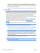
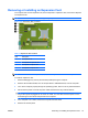
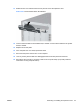

7. Rotate up the external drive bay housing to access the memory module sockets on the system
board.
Figure 2-8 Rotating the Drive Cage Up
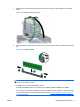
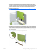
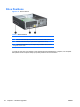
8. Open both latches of the memory module socket (1), and insert the memory module into the socket
(2).
Figure 2-9 Installing a DIMM
NOTE: A memory module can be installed in only one way. Match the notch on the module with
the tab on the memory socket.
A DIMM must occupy the black DIMM1 socket.
Populate the DIMM sockets in the following order: DIMM1, DIMM3, DIMM2, then DIMM4.
For maximum performance, populate the sockets so that the memory capacity is spread as equally
as possible between Channel A and Channel B. Refer to
Populating DIMM Sockets on page 15
for more information.
ENWW Installing Additional Memory 17