
Using the Node Management Services (NMS) Utilities (MPE/iX 7.0, 7.5)


Chapter 4 59
Using NMMGR Utility Screens
Output Configuration File Screen
to the right of “Print Summary” and press the [Print Summary] key. (The
numbers for the subsystems are the same as those that you would use
to select subsystems for the
[Print Data] key.)
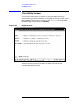
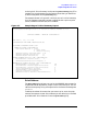
The example shown in Figure 4-5 is the first part of a critical summary
for a full-gateway node that has been configured with a point-to-point
(router) network interface (NI) and a LAN NI.
Figure 4-5 Sample Page of Critical Summary Report
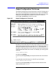
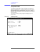
Print Subtree
The [Print Subtree] key allows you to print the NMMGR data screens for
a specified subtree. By default, output is sent to the device LP. You can
redirect the output by using a file equation for the formal file designator
FORMLIST.
To define the subset of screens that you want to print, enter the path
name of the topmost screen of the subtree you are selecting in the field
provided under “Print Subtree.” Press the
[Print Subtree] key.
NM Configuration Manager 32098-20016 V.uu.ff (C) Hewlett Packard Co. 1990
CRITICAL SUMMARY - NETXPORT CONFIGURATION
TUE, APR 10, 1990, 11:07 AM
CONFIGURATION FILE NAME: NMCONFIG.PUB.SYS
NODE NAME: FLAGSTAFF.ROUTE66.USA
TRANSPORT GLOBAL CONFIGURATION:
name Search Method: 1. Probe
2. Probe Proxy
3. Network Directory
Maximum Directly Connected Nodes: 1024
Maximum Outbound Destinations: 360
Maximum Inbound Destinations: 360
PACKET EXCHANGE PROTOCOL (PXP) CONFIGURATION:
Retransmission Interval (Secs): 10
Maximum Retransmissions Per Request: 4
TRANSMISSION CONTROL PROTOCOL (TCP) CONFIGURATION:
Maximum Numbre of Connections: 128
Retransmission Interval Upper Bound (Secs): 180
Retransmission Interval Lower Bound (Secs): 4
Initial Retransmission Interval: 5
Maximum Number of Retransmissions: 4
Connection Assurance Interval: 600
Maximum Connection Assurance Retransmissions: 4
.
.
.