
System Debug Reference Manual (32650-90888)

Chapter 6 237
System Debug Command Specifications M-X
MR
NOTE
the Precision Architecture and Instruction Reference Manual refers to the PC
(
program counter
) registers as the IA (
instruction address
) registers.
This manual will use the PC mnemonic when referring to the IA registers.
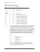
The following registers are floating-point registers. If a machine has a
floating-point coprocessor board, these values are from that board. If no
floating-point hardware is present, the operating system emulates the
function of the hardware, in which case these are the values from
floating-point emulation.
none
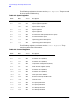
PCQF dM PC queue (PCOF.PCSF) front
none
PCQB dM PC queue (PCOB.PCSB) back
none
PC dM PCQF with priv bits set to zero
none
PRIV dM Low two order bits (30,31) of PCOF.
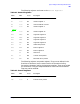
CR19 IIR dM Interrupt instruction register
CR20 ISR dM Interrupt space register
CR21 IOR dM Interrupt offset register
CR22 IPSW dM Interrupt processor status word
PSW dM Processor status word
CR23 EIRR dM External interrupt request register
CR24 TR0 dM Temporary register 0
[vellip]
CR31 TR7 dM Temporary register 7
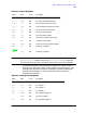
Table 6-5. Floating Point Registers
Name Alias Access Description
FP0
none
dm FP register 0
FP1
none
dm FP register 1
FP2
none
dm FP register 2
FP3
none
dm FP register 3
FP4
FARG0
dm FP argument register 0
FRET
dm FP return register
FP5
FARG1
dm FP argument register 1
Table 6-4. Control Registers
Name Alias Access Description