
System Debug Reference Manual (32650-90888)

Chapter 4 127
System Debug Command Specifications :-Exit
DR
NOTE
The Precision Architecture and Instruction Reference Manual refers to the PC
(program counter) registers as the IA (instruction address) registers. This
manual will use the PC mnemonic when referring to the IA registers.
The following registers are floating-point registers. If a machine has a floating-point
coprocessor board, these values are from that board. If no floating-point hardware is
present, the operating system emulates the function of the hardware; in that case these
are the values from floating-point emulation.
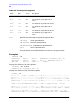
CR22 IPSW dM Interrupt processor status word
PSW dM Processor status word
CR23 EIRR dM External interrupt request register
CR24 TR0 dM Temporary register 0
[vellip]
CR31 TR7 dM Temporary register 7
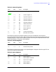
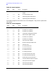
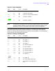
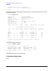
Table 4-5. Floating Point Registers
Name Alias Access Description
FP0
none
dm FP register 0
FP1
none
dm FP register 1
FP2
none
dm FP register 2
FP3
none
dm FP register 3
FP4
FARG0
dm FP argument register 0
FRET
dm FP return register
FP5
FARG1
dm FP argument register 1
FP6
FARG2
dm FP argument register 2
FP7
FARG3
dm FP argument register 3
FP8
none
dm FP register 8
[vellip]
FP15
none
dm FP register 15
FPSTATUS
none
dm FP status reg(left half of FP0)
FPE1
none
dm FP exception reg 1 (right half of
FP0)
Table 4-4. Control Registers
Name Alias Access Description