
SNA Link/iX Node Managers Guide (30291-90507)

74 Chapter2
SNA Node and Link Configuration
Configuring the SNA Node and Link
If you specify a value greater than 0, you must also
specify the Call Retry Delay field.
Note that this field is valid only when OUT is specified
for the Call Direction field.
Range: 0-999 (integer)
Default: 3
Call Retry Delay
Conditionally required. The number of seconds the
QLLC module waits between attempts to connect to the
remote system.
This field is required
only
if a value greater than 0 is
specified for the Maximum Call Retries field.
Note that this field is valid only when OUT is specified
for the Call Direction field (described earlier in this
chapter).
Range: 60-999 (integer)
Default: 60
File:
For display only. The name of the configuration file.
Once you have entered the X.25 link information, press
[f6] (Save Data).
After the information is saved, press
[f8] (Prior
Screen) until you get to the screen you need next.
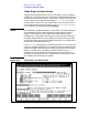
Before Using the X.25 Link Data Screen
The PVC or SVC that SNA/X.25 Link is going to use must have already
been defined in the X.25 System Access configuration and the DTC
Manager configuration or the DTS configuration. Before configuring the
X.25 link parameters and virtual circuit data on the screen shown in
Figure 2-8, “X.25 Link Data Screen,” the following tasks must be
performed.
For an SNA/X.25 PVC:
• Configured a logical channel identifier (LCI) range in the DTC
Manager configuration or the DTS configuration. The PVC Number
you specify on the screen shown in Figure 2-8, “X.25 Link Data
Screen,” the screen must be within the LCI range you configured.
• Configured a network interface (NI) for the SNA/X.25 PVC in the
X.25 System Access configuration. The value you specify for NS
Network Interface Name on the screen shown in Figure 2-8, “X.25
Link Data Screen,” must match the NI name you configured.