Performing System Management Tasks 900 Series HP 3000 Computer Systems ABCDE HP Part No. 32650-90004 Printed in U.S.A.
The information contained in this document is subject to change without notice. Hewlett-Packard makes no warranty of any kind with regard to this material, including, but not limited to, the implied warranties of merchantability or tness for a particular purpose. Hewlett-Packard shall not be liable for errors contained herein or for direct, indirect, special, incidental or consequential damages in connection with the furnishing or use of this material.
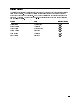
Printing History The following table lists the printings of this document, together with the respective release dates for each edition. The software version indicates the version of the software product at the time this document was issued. Many product releases do not require changes to the document. Therefore, do not expect a one-to-one correspondence between product releases and document editions.
iv
Preface MPE/iX, Multiprogramming Executive with Integrated POSIX, is the latest in a series of forward-compatible operating systems for the HP 3000 line of computers. In HP documentation and in talking with HP 3000 users, you will encounter references to MPE XL, the direct predecessor of MPE/iX. MPE/iX is a superset of MPE XL. All programs written for MPE XL will run without change under MPE/iX.
In This Book This manual is your guide to the system manager tasks for the 900 Series HP 3000. Chapter 1 Starting the System explains the di erent ways to start your computer, how to install a new operating system, and how to use the initial system loader's standalone utilities. Chapter 2 Getting Started De ning Your System explains how to use SYSGEN to con gure your system and introduces the other con gurators (which are fully explained in the chapters that follow.
Conventions UPPERCASE In a syntax statement, commands and keywords are shown in uppercase characters. The characters must be entered in the order shown; however, you can enter the characters in either uppercase or lowercase. For example: COMMAND can be entered as any of the following: command Command COMMAND It cannot, however, be entered as: comm italics com_mand In a syntax statement or an example, a word in italics represents a parameter or argument that you must replace with the actual value.
Conventions (continued) [ ... ] In a syntax statement, horizontal ellipses enclosed in brackets indicate that you can repeatedly select the element(s) that appear within the immediately preceding pair of brackets or braces. In the example below, you can select parameter zero or more times. Each instance of parameter must be preceded by a comma: [,parameter][...
Contents 1. Starting the System Starting the System . . . . . . . . . . . . To save main memory to tape . . . . . . Using Initial System Loader (ISL) Commands Using the Standalone ISL Utilities . . . . . To set or change the system clock . . . . . To list system hardware . . . . . . . . . To recover corrupted disk les . . . . . . To recover les with SAVE . . . . . . . . To enable the access port (AP) . . . . . . To use the access port . . . . . . . . . . . . . . . . . . . . . . . . . . . . . . . . . . .
To specify the RSIZE . . . . . . . . . . . . . . . To specify the OUTDEV . . . . . . . . . . . . . . To create a streams device . . . . . . . . . . . . . To specify the MODE . . . . . . . . . . . . . . . To specify the CLASS . . . . . . . . . . . . . . . To specify the CMODE . . . . . . . . . . . . . . To specify the PMGR . . . . . . . . . . . . . . . To specify the LMGR . . . . . . . . . . . . . . . To specify the PMGRPRI . . . . . . . . . . . . . To specify the MPETYPE and MPESUBTYPE . . .
To con gure a UPS . . . . . . . . . . . . . . To con gure the rst UPS on a Series 9X8 . . . . To con gure a UPS connected via a DTC port . . To use UPS Monitor/iX software . . . . . . . . System behavior when AC power fails . . . . . . System Behavior When AC Power Returns . . . . To enable logging of UPS activity . . . . . . . . To review UPS activity recorded in the system log . . . . . . . le . . . . . . . . . . . . . . . . . . . . . . . . . . . . . . . . . . . . . . . . . . . . . . . . . . . . .
6. De ning Miscellaneous System Resources Using the Miscellaneous Con gurator . . . . . . To access the MISC con gurator . . . . . . . To use online help . . . . . . . . . . . . . . To show current values . . . . . . . . . . . To print current values . . . . . . . . . . . To con gure I/O-related parameters . . . . . . To con gure job-related limits . . . . . . . . To display resource identi cation numbers (RINs) To delete RINs . . . . . . . . . . . . . . . To set resource allocations . . . . . . . . . .
8. Allowing Access to the System POSIX on MPE/iX . . . . . . . . . . . . . . The Hierarchical File System (HFS) . . . . . . Expanded File Naming Syntax . . . . . . . . MPE/iX Shell and Utilities . . . . . . . . . Setting Up Accounts, Groups, and Users . . . . . File Ownership . . . . . . . . . . . . . . . The Group and User Databases . . . . . . . . To create accounts . . . . . . . . . . . . . To create MPE groups . . . . . . . . . . . . To create users . . . . . . . . . . . . . . .
To de ne the volume set . . . . . . . . . . . . . . . . . . . . To add members to the volume set . . . . . . . . . . . . . . . To create volume classes . . . . . . . . . . . . . . . . . . . . To add additional volumes to an existing volume class . . . . . . . To display information about volume sets . . . . . . . . . . . . Managing Permanent and Transient Storage . . . . . . . . . . . . To con gure disk storage . . . . . . . . . . . . . . . . . . . . To change the disk storage . . . . . . . . . . . . . . .
12. System Hardware Descriptions Identifying the System . . . . . . . . . . . . . . . . . . . . Components of the Series 9x7LX and 9x7 Systems . . . . . . . Components of the Series 9x8LX and 9x8 Systems . . . . . . . Components of the Series 920 Through Series 958 Systems . . . . Components of the Series 925 Through Series 949 Systems . . . . Switches and Lights on Series 925 Through Series 949 Systems . To remove the SPU Card Cage . . . . . . . . . . . . . . . To understand the CIO expander . . . . . . .
Figures 1-1. 7-1. 8-1. 8-2. 9-1. 9-2. 9-3. 9-4. 9-5. 9-6. 10-1. 10-2. 12-1. 12-2. 12-3. 12-4. 12-5. 12-6. 12-7. 12-8. 12-9. 12-10. 12-11. 12-12. 12-13. 12-14. 12-15. Enabling the Access Port . . . . . . . . . . . . . Threshold Manager Global Con guration Display . . . MPE/iX File System (Prior to Release 4.5) . . . . . MPE/iX File System (Release 4.5 and Later) . . . . . Master and Member Volumes . . . . . . . . . . . . Data Partitioning with Classes . . . . . . . . . . .
Tables 2-1. 2-2. 5-1. 6-1. 6-2. 6-3. 6-4. 7-1. 8-1. 8-2. 8-3. 8-4. 8-5. 8-6. 9-1. 12-1. 12-2. 12-3. 12-4. 12-5. 12-6. 12-7. The Con gurator Commands . . . . . . TAPE Command Parameters . . . . . . SYSFILE Con gurator Command Matrix Values for JOB Parameters . . . . . . . Values for RESOURCE Parameters . . . Values for SESSION Parameters . . . . Values for STACK Parameters . . . . . Threshold Manager Commands . . . . . Selected MPE/iX Shell Commands . . . Capabilities . . . . . . . . . . . . .
1 Starting the System System startup refers to the procedure for starting the computer operating system and other programs. It does not refer to physically installing the hardware, loading the fundamental operating system (FOS), or to turning on the power to the computer, disk drives, tape drives, printers, or the system console. (Normally, computer hardware remains powered on.) As the system manager, you need to know when to start the system and when and why to shut it down.
Starting the System There are four occasions when you are required to start your system: after your system has failed and you have saved main memory to tape after you have updated or changed the system before and after installation of the operating system and con guration after you have shut down the system To save main memory to tape Use the DUMP utility to perform a memory dump after a system failure or hang, for a recurring system problem, or when the system fails to boot properly.
Using Initial System Loader (ISL) Commands You use Initial System Loader (ISL) commands to display or change boot path information or to initiate the ISL utilities. The commands are listed and brie y explained in the following table. To issue one of them, enter the command at the ISL prompt (ISL>).
To set or change the system clock The ISL utility CLKUTIL reads and sets the hardware clock, which is maintained either by a Battery Backup Unit (BBU) or an Uniterruptible Power Supply (UPS), depending on the system. This clock maintains Greenwich Mean Time (GMT) independently of the software clock that is displayed when you enter the ISL START utility or any of the other ISL utilities that support the software clock.
SHOWCLOCK displays the system time in the hh:mm:ss format, the current time correction and the time zone. SETCLOCK changes the system time by introducing a time correction into the system that is gradually consumed. By doing so, it allows for negative time corrections (i.e. \setting the clock back"), that do not adversely a ect system accounting, database logging and recovery systems and other user applications that rely on the forward progression of time.
d Below is an example of an IOMAP listing for a Series 935: IOMAP revision 2807 February 19, 1988 a IOMAP Running: ce81 This program has the capability to identify the configuration of the system and its I/O paths and devices. Many of the components of the I/O system can be tested with self-test and loopback diagnostics. Without changing any parameters, this program will map all existing I/0 components in the system, but does not perform any other diagnostics.
d a I/0 Configuration: Type Path Component Name ID ------------ -------------------------------------- ---0 Native Processor 0H 4 CIO Channel Adapter 8H 4.1 HP-IB card 2H 4.1.0 7937H disc drive 214H 4.1.1 7937H disc drive 214H 4.1.2 7937H disc drive 214H 4.1.3 7937H disc drive 214H 4.1.4 7937H disc drive 214H 4.2 Console Device Adapter 4.3 LAN card 6H 4.4 LAN card 6H 24 Memory Controller 1H 28 Memory Controller 1H 32 Memory Controller 1H 36 CIO Channel Adapter 8H 36.5 HP-IB card 2H 36.5.
Below is a list of the commands available to you in DISCUTIL and a brief explanation of each one. Command CONFIGURE DISMOUNT DO DSTAT EXIT HELP LISTREDO MOUNT PDEV REDO SAVE SHOWDEV TAPE UNCONFIG De nition Con gures additional devices. Dismounts a disk volume making it inaccessible to DISCUTIL . Re-executes a command from the command history stack after allowing you to make changes to it. Displays information about each mounted volume. Terminates DISCUTIL . Lists available commands.
HELP MOUNT To display the command line history stack, enter LISTREDO. To modify and re-execute one of the commands, use the REDO command. To simply re-execute the command, use DO.
Indicate the le(s) that you want copied to tape. The le(s) must reside on a disk de ned during startup of DISCUTIL or with the CONFIGURE command. You can replace the lename, groupname, and acctname parameters by @ to indicate all members of the set. The prompt repeats after the le set is saved. To terminate SAVE, press 4RETURN5. 3. To save les from a speci c device enter the LDEV number and press 4RETURN5 at the ENTER THE LDEV: prompt.
d Below is a short example of the interaction between user and DISCUTIL during SAVE: a discutil>SAVE ENTER FILE SET TO BE SAVED: MYFILE.JOHN.SMITH ENTER THE LDEV: 3 ENTER THE MODIFICATION DATE(MM/DD/YYYY):06/25/1990 ENTER THE TAPE LDEV: 7 MYFILE MYFILE c .JOHN .JOHN .SMITH - LDEV 3 - ADDR $0002CA0 - FOUND .SMITH - LDEV 3 - ADDR $0002CA0 - SAVED ENTER FILE SET TO BE SAVED: b To enable the access port (AP) The access port allows you to use 4CTRL5 B commands.
To use the access port The commands you use to control activity of the access port are listed below: Command CA CO DI DR DS ER ES HE RS SE TA TC TE 1-12 De nition Con gures the system's remote support modem port. Returns the console from control mode to console mode. Disconnects the line to a remote console. Disables access to the system by a remote console. Disables the display of the system status line during console mode. Enables access by a remote console.
2 Getting Started Defining Your System As system manager, your responsibilities include con guring your system when it is initially installed and adding or changing devices as time goes on. When your system is delivered, it includes a tape with default con guration information. To modify the system con guration, you use the system generator (SYSGEN) and either copy the changes to a system load tape (SLT), or copy them to disk in a con guration group.
Configuring Your System with SYSGEN As system manager, you use the system generator (SYSGEN) to make changes to the con guration of your computer system. The con guration of a system is like a map; it tells the computer what peripherals are attached to it and where they are attached. Any device that is not con gured, or con gured incorrectly, cannot communicate with the system. To access SYSGEN To start SYSGEN and use any of the rst-level commands available to you, do the following: 1.
To confirm potentially serious actions SYSGEN is initially set to have you con rm potentially serious actions. For example, if you make con guration changes and forget to save them before you exit, SYSGEN prompts you to do so. This feature (PERMYES OFF) can help prevent time-consuming mistakes. You have the option of enabling PERMYES so that SYSGEN will automatically answer YES to any prompt. You may want to do so, for example, when you are initiating a job.
Table 2-1. The Configurator Commands SYSGEN Command IO LOG MISC SPU SYSFILE De nition Starts the input/output con gurator, which you use to de ne the local devices for a host or target system. Starts the LOG con gurator, which you use to de ne which system and user events are recorded. Starts the MISC con gurator, which you use to de ne miscellaneous system elements such as job- and session-related processes, system resource allocation, spool parameters, stack and heap sizes, and other information.
For example, to display detailed information and syntax of the SYSGEN KEEP command, enter: sysgen>HELP KEEP Or, to display the syntax for the IO con gurator command ADEV, start the IO con gurator and enter: io>HELP ADEV To show the state of the configurators Use the SHOW command to display the current state of global SYSGEN information. For example, use SHOW to nd out the version you are using or what the status of the PERMYES option is. You can also display a combined listing of con gurator information.
system with the START NORECOVERY option. Other changes take e ect only when you perform an update with the system load tape (SLT). To make changes in a con gurator, hold and then keep the changes, follow these steps: 1. At the console, log on as MANAGER.SYS by entering: HELLO MANAGER[/userpass].SYS[/acctpass] 2. Start SYSGEN and access the con guration group that you plan to store on the system load tape (SLT). The default is the name of the group used in the most recent system boot, usually CONFIG. 3.
TAPE has the following syntax: 2 TAPE 6 6 62 6 6 MODE 6 6 4 8 93 VERBOSE > > > > > > 7 > > > > NOCHANGE > > > >7 < = 3 NOCONFIG 7 7 2 = STORE 7 > NODIAG > 7 > > > >7 > > NOLOGNUM > >5 > > > > : ; = leset 3 22 3 DEST = OFFLINE 3 LOGNUM Table 2-2. TAPE Command Parameters Parameter VERBOSE NOCHANGE NOCONFIG NODIAG NOLOGNUM LOGNUM OFFLINE STORE De nition Lists the number of nonuser les to be saved and the name of e ach le as it is saved to the boot tape.
To create a system load tape with the new information: 1. Make and hold all necessary changes to the con guration. 2. Enter the EXIT command to exit the con gurator and return to the SYSGEN prompt. 3. Enter the KEEP command, followed by groupname to store all changes to a set of permanent disk les. The parameter, groupname is the group in the SYS account that contains the con guration data le set to be used.
Cross-Validating NMCONFIG. PUB.SYS with SYSGEN One of the system manager's jobs is to con gure terminals, printers, the local area network (LAN) and all Uninterruptible Power Supply (UPS) units that are not hard-wired on your system. To do so, you use the node management services network manager program, or NMMGR. After you are nished running NMMGR and have validated the con guration le you created, you must cross-validate it with the con guration le you created with SYSGEN.
3 Defining Input/Output Devices With the introduction of version C.55.00 of MPE/iX, there are two ways to de ne input and output devices on a system: using SYSGEN's I/O Con gurator or using the IOCONFIG utility. Both methods provide information about the input and output devices con gured on a system and let you make changes to the con guration as necessary.
Using SYSGEN's I/O Configurator You can use the I/O con gurator to display information about the current system con guration and to make any necessary changes to it. To access the I/O con gurator, do the following: 1. At the MPE prompt, start SYSGEN by entering: :SYSGEN 2. At the SYSGEN prompt (sysgen>), enter: sysgen>IO First you see a list of the commands available to you. To issue a command, you can enter either the full command name or the abbreviation shown in parentheses.
Viewing the current configuration To get information about the current con guration, either displayed on screen or printed, using the LCLASS, LDEV, LPATH, and LVOLcommands as described in the following table. Command Lists the Lists the Lists the Lists the LCLASS LDEV LPATH LVOL De nition speci ed class names and the devices assigned to each one. attributes of the speci ed logical devices. attributes of the speci ed paths. attributes of the speci ed volume set member.
To list devices Each con gured logical device (LDEV) is assigned a unique LDEV number which identi es a physical device associated with a system. Use the LDEV command (abbreviated LD) to list the characteristics of the I/O devices con gured for your system. You can list all devices, a subset of them, or a speci c device.
To list paths Use the LPATH command to display information about the adapters and I/O devices on a speci ed path level. LPATH lists the con gured I/O paths according to their path, hierarchy level, or associated I/O manager. To display I/O path information, at the I/O Con gurator prompt (io>), enter: io>LPATH parameters LPATH has the following parameters: 22 3 PATH 3= path LPATH (LP) 22 3 DEST = OFFLINE 3 22 3 LEVEL = # 3 22 3 MANAGER = managername,...
To list volumes A volume is one disk pack. Each volume is a member of a volume set and contains a volume label, a label table, and a free space map. To list volumes, at the I/O Con gurator prompt (io>), enter: io>LVOL LVOL has the following parameters: LVOL (LV) 22 3 2 VNAME = volumename, volumename 32 . .. 33 22 3 DEST = ``OFFLINE'' 3 The following list brie y explains how to use the LVOL command and provides examples. Use this command To do this LVOL List volume information for all volumes.
Configuring Devices with SYSGEN There are two general categories of devices that you con gure on your computer system, local devices and non-local devices. Local devices are \hard-wired" or connected via parallel cables to your computer. These include tape and disk drives and some printers. You con gure local devices with SYSGEN's I/O Con gurator. You may also con gure I/O devices with the IOCONFIG utility, explained later in this chapter.
To configure default device attributes There are additional attributes for local devices that you can or must leave set to the default. They include device type, associated output device, device mode and device class, which are described next. A number of other attributes that you can con gure are explained throughout this chapter. A logical device is identi ed by its type, which you cannot change. Device types names are standardized, and each logical device may be only one type.
Command De nition Creates a new class name and associates devices to the new class. Adds an I/O device to the system. De nes the I/O path to an adapter. The path must not have already been de ned. Adds a new volume to the system volume set con guration. ACLASS ADEV APATH AVOL You use the NMMGR program to add non-local devices such as terminals, serial printers, UPS hardware and other objects to a system.
To add a class name, enter the ACLASS command, the class name, and the LDEV associated with it. For example, to add the class name EPOC and associate it with LDEV 19, enter: io>ACLASS EPOC 19 To assign a mode to a device You can assign a mode to the device or accept the default mode assigned by SYSGEN. To assign a mode, enter the ACLASS command, the class name, the LDEVs, and the keyword or positional MODE parameter.
To add a device, at the I/O Con gurator prompt (io>), enter: io>ADEV ldev pathid otherparameters ADEV has the following parameters: ADEV (AD) 22 82 3 3 LDEV = #/#,#,...
To specify the LDEV, PATH, and ID. LDEV, PATH, and ID parameters. When you issue the ADEV command, you must specify the Use LDEV to specify the logical device number for the device you are adding. Use PATH to specify the physical path to reach a device. Use ID to specify the device you are adding. For example, to add an HP2688A printer as LDEV 17 (using keyword parameters), enter: io>ADEV LDEV=17 PATH=4.3.
io>ADEV 10 2/4.2.3 HP7978B MODE=(JOB,DATA) OUTDEV=LP& RSIZE=128 CLASS=JOBTAPE You can also use the intrinsic HPDEVCREATE to create a streams le. The parameters you enter, such as device le type, LDEV, major number, minor number and link name, de ne the le. For more information, read MPE/iX Intrinsics Reference Manual (32650-90028). The MODE parameter speci es the device operation mode. Your choices for mode and their meanings are de ned below: To specify the MODE.
The CMODE parameter overrides the default class mode for a device. For example, to make all HP7978B tape drives that you are adding to your system output devices only, enter: To specify the CMODE. io>ADEV 40 4.1.7 HP7978B CLASS=TAPE CMODE=OUT If the class already exists, the CMODE entry is ignored. The values for the CMODE parameter are de ned in the table below.
The DEVNAME associates a device name with a particular LDEV number, which allows a user to specify the device by name instead of by number. When choosing device names, remember the following rules: A device name must begin with a letter. You cannot use a device name of exactly eight characters that begins with the letter \D" followed immediately by one or more digits. You cannot use the name \VTERM." No two logical devices may have the same device name.
The le name that you enter follows MPE-escaped syntax rules. So, to create a device link le in a directory other than the current working directory, include the path in the le name. For example, to create the device link le tape7 in the dev directory, enter: :"/dev/tape7/c,0,7" You may also use three other methods to create device link les: the mknod POSIX C-library function, the HPDEVCREATE intrinsic, or the MPE/iX shell utility mknod.
You must specify the PATH and ID parameters with the APATH command. If you specify a path that already exists, an error occurs. The product ID is either the Hewlett-Packard product number or a mnemonic name that designates di erent uses of the same product. To specify the PATH and ID. For Series 925 through Series 949 systems and for Series 958 systems, you describe the path as follows: the channel adapter the channel adapter and device adapter separated by a period (such as 4.
To specify the MAXIOS. MAXIOS tells the device manager how many concurrent IOs to expect. For example, to specify 20 concurrent I/O devices, enter: io>APATH PATH=4.2 ID=HP27113A PMGRPRI=5 MAXIOS=20 Normally, you do not specify this value. Instead, the I/O default le usually speci es zero, which allows the manager to set itself to its default. To add volumes Use the AVOL command (abbreviated AV) to add a new volume to the system volume set con guration.
Parameter De nition Modi es the I/O path from one that exists to a new path that does not already exist. Changes I/O class information. Changes the attributes of a con gured device. Changes the attributes of an I/O path. Modi es the attributes of a volume set member. MADDRESS MCLASS MDEV MPATH MVOL To modify paths An address is an I/O path identifying a speci c I/O device.
82 3 9 22 3 3 NEWCLASS = newclassname CLASS = classname MCLASS (MC) 3 3 3 22 22 3 DLDEV = devicerange[,devicerange][...] ALDEV = devicerange[,devicerange] [...] 93 8 2 IN > > > > > > 7 6 > > OUT > > 6 > > =7 < 7 62 3 CIO 7 6 MODE = 7 6 NCIO > > 7 6 > > > > > 5 4 > > RANDOM > > > ; : DEFAULT You must enter the CLASS parameter and at least one other parameter. Parameter NEWCLASS ALDEV DLDEV MODE De nition Changes the name of the class. The new name must not exist prior to using NEWCLASS .
To modify devices Use the MDEV command (abbreviated MD) to modify the attributes of a device. You enter the command, the LDEV number of the device you want to change, and at least one other parameter. You cannot use the MDEV command to change a Hewlett-Packard supported device to a USER (unsupported) device.
Parameter LDEV NEWLDEV ID PATH CLASS MODE OUTDEV RSIZE PMGR and LMGR PMGRPRI MPETYPE and MPESUBTYPE DEVNAME Note 3-22 De nition Speci es which devices to modify. If a speci ed device number does not exist, SYSGEN issues a warning. Gives the new device numbers associated with the speci ed devices. The number of devices given must match the number of devices speci ed in the LDEV parameter. Changes the product ID associated with the devices.
For example, to make LDEV 10 the streams device with LP as the output device, enter: io>MDEV 10 MODE=(JOB,DATA) OUTDEV=LP To modify I/O paths Use the MPATH command (abbreviated MP) to modify the attributes associated with an I/O path.
To change the name of the physical device manager, use the MPATH command followed by the PMGR parameter and the new name. For example, to rename the device manager on a Series 925 through 949 system or a Series 958 system, enter: To change the name of the physical device manager. io>MP 4.1 PMGR=HPIB_DAM Or, to rename the device manager on a Series 950 through 980 system, enter: io>MPATH 2/4.3 PMGR=HPIB_DAM If you change the ID parameter and do not use the PMGR parameter, SYSGEN uses the default.
Deleting Objects in SYSGEN When you use SYSGEN to delete objects from the system con guration, there are four I/O Con gurator commands available to you: DCLASS, DDEV, DPATH, and DVOL. They are de ned in the table below and explained in the following sections. Parameter De nition Removes one or more class names from the system. Removes a speci c device, range of devices, all products of a given product identi cation, all devices of a given type, or all devices of a given class name.
DDEV (DD) 3 82 LDEV = #/#,#,... > 3 > <2 9 > > = ID = deviceid 3 TYPE = > devicetype > > > 3 ; :2 CLASS = classname 2 You must enter at least one parameter and the speci ed device must exist in the current con guration or SYSGEN will issue a warning. Other errors that occur are typically due to improper entry of a logical device, a range, or improper value for a positional parameter. The following list brie y explains how to use the DDEV command and provides examples.
To delete paths Use the DPATH command (abbreviated DP) to delete an I/O path and, optionally, all I/O paths below it from the con guration. If there are I/O paths below the one you are deleting, SYSGEN prompts you before deleting them with this question: I/O path specified has pending devices, want to delete all of them (yes/no)? If an I/O path is currently used by a con gured device, SYSGEN issues an error and does not delete the path. 1. Start SYSGEN and at the prompt (sysgen>), enter: sysgen>io 2.
1. Make the necessary changes to the con guration with the I/O Con gurator. (This process is no di erent than it was before; for more information, read the previous section of this chapter \Using SYSGEN's I/O Con gurator". 2. Keep the con guration changes and exit SYSGEN. The information is saved in the le LOG4ONLN.PUB.SYS, which is used by the DOIONOW command. 3. At the CI prompt, execute the DOIONOW command by entering: :DOIONOW 4.
You may use IOCONFIG in one of two ways: interactively or non-interactively which is sometimes called \command mode". To use IOCONFIG interactively, you issue the IOCONFIG command, without command parameters, at the CI prompt. This starts the IOCONFIG utility, at which point you may enter any of the commands shown in the following table at the special prompt. When you are through using IOCONFIG, you must explicitly exit the utility.
Adding a device with IOCONFIG To con gure a tape drive, disk or a system printer into the system, the system manager or operator uses the ADDDEVICE or ADEV command. The syntax of the command is identical to that of SYSGEN's ADEV command in IO level, except that the ID parameter is optional. The command syntax is as follows: ADDDEVICE 22 3 6 6 6 6 6 62 6 6 MODE 6 6 6 6 6 4 22 22 22 22 22 3 LDEV = #/#,#, . . .
Listing one or more devices with IOCONFIG The system manager or operator can list all devices in the system or one or more speci ed devices along with their con guration information using the LISTDEVICE or LDEV command. When you enter either command without parameters, information about all devices currently con gured in the system is listed. By providing one or more parameters as the selection criteria, you can see information about particular devices.
Adding a device class with IOCONFIG To create a new device class in the system, the system manager or operator uses the ADDCLASS or ACLASS command. The syntax of the ACLASS command is identical to that of ACLASS in SYSGEN. All devices that you designate as members of the class (using the LDEV parameter) must be con gured before issuing this command. With the release of version C.55.00 of MPE/iX, the maximum number of devices that you can con gure has substantially increased.
Listing one or more device classes with IOCONFIG The system manager or operator can list all device classes in the system, or one or more speci ed device classes, with their con guration information using the LISTCLASS or LCLASS command. When no parameter is used with this command, all device classes currently con gured in the system are listed. By providing the names of those device classes with the CLASS keyword, you can view information about particular device classes.
Listing an I/O path with IOCONFIG An I/O path is the system address assigned to the device interface hardware and the physical path used to reach an I/O device. The system manager or operator can use the LISTPATH command to display information about adapters and I/O devices on a speci ed path in the active con guration. The command lists the con gured I/O paths according to their paths or to their associated I/O manager.
Adding an HP-IB Disk Drive The master disk on any system, which is LDEV 1, should not be smaller than 400 megabytes. A disk this size or smaller is too small to run the operating system and its subsystems. However, you can use disks of this size to store application programs and user les. Once you use the I/O Con gurator to add an HP-IB disk drive, you must keep the changes, create a new SLT, and reboot the system for the addition to take e ect.
10. Use the ADEV command to add the drive to the path you speci ed. Be sure to include the device address. For example, to add the drive as LDEV 4, enter: io>ADEV LDEV=4 PATH=36.2.0 ID=HP7937H CLASS=DISC 11. Enter the HOLD command to hold all changes. 12. Enter the EXIT command to exit the I/O Con gurator. 13. At the sysgen> prompt, enter the KEEP command and a group name to save changes in a permanent le. 14.
To configure a UPS You can use one of two con guration methods to add UPS devices to a Series 9X8 systems. For the rst or only UPS, which is attached to the third serial port on the system's LAN/Console I/O interface card, you do most of the con guration with SYSGEN. For additional UPS devices, which are attached to a DTC serial I/O port, you add them to the con guration primarily using the NMMGR program. (As the nal step in this second method, you will cross-validate the con guration les with SYSGEN.
Note Each UPS device, and only a UPS device, MUST have its device class name set to HPUPSDEV during I/O con guration. Otherwise, the UPS Monitor software will not be able to initialize and communicate with the UPS device(s) correctly. To configure a UPS connected via a DTC port On a Series 9X8 system, all UPS devices other than the rst one are connected to your computer system via a DTC port. On a Series 991 and 995 system, all UPS devices (including the rst one) are connected via a DTC port.
To use UPS Monitor/iX software Once you have con gured UPS devices on the system, they will automatically be monitored by the UPS Monitor/iX software. This software causes the UPS devices to emulate the traditional battery backup method of system powerfail handling and recovery and, in addition, provides system console messages and system log le entries describing UPS hardware conditions. The UPS Monitor/iX process behaves in one of two ways, depending on the system on which Release 5.
d AC power has failed. In the following example, UPS Monitor/iX reports and power failure and a recovery shortly thereafter: :showtime FRI, AUG 13, 1993, 11:27 AM : :11:27/50/UPS LDEV 102 reports loss of AC input power. (UPSERR 0033) a **RECOVERY FROM POWER FAIL** 11:27/50/UPS LDEV 102 reports AC input power restored. (UPSWRN 0036) c : b Example 3-6. Sample Console Messages from UPS Monitor/iX UPS Monitor/iX also writes a system log le entry that denotes the input power loss to the UPS device.
2. At the sysgen> prompt, start the LOG con gurator by entering: sysgen>LOG 3. To display which system logging events are enabled or disabled, enter: log>SHOW SLOG 4. To turn UPS Monitor/iX logging on (if it is currently listed as OFF), enter: log>SLOG ON=148 5. To exit the LOG con gurator and SYSGEN, enter the EXIT command twice. You will see the MPE prompt displayed on your screen.
4 Defining Events to Be Recorded One of your tasks as system manager is to use the SYSGEN LOG con gurator to establish which system and user events are recorded in log les. System logging records certain system resource usage information by accounts, groups, and users on a job or session basis. For example you might decide to log failed attempts to enter passwords for the purpose of monitoring system security.
Using the LOG Configurator You use the LOG con gurator to display information about system and user logging, print log les, and choose which events the system will record. To enter the LOG configurator You make all system and user logging changes from with the LOG con gurator, which is one of the SYSGEN modules. To enter the LOG con gurator, do as follows: 1. At the MPE prompt, start SYSGEN by entering: SYSGEN 2.
To show current LOG values Use the LOG con gurator's SHOW command to display current LOG values on the system console or to print them o ine. At the LOG prompt (log>), enter: log>SHOW parameters SHOW has the following parameters: 2 SHOW 4 2 COMMAND Parameter SLOG ULOG ALL OFFLINE 8 93 SLOG = 3< 22 = ULOG 5 DEST : ; ALL 3 = OFFLINE 3 De nition Lists the state of the system logging events. Lists the number of user logging processes and users per logging process currently con gured.
To see all logging information To display all currently con gured values, you can enter: log>SHOW Or, you can enter: log>SHOW ALL The LOG Con gurator displays the minimum, maximum and current value for user log events and the name, number and status (OFF or ON) of system log events. To print current logging information Instead of displaying logging information on the console, you can print it o ine. To do so, add the DEST=OFFLINE parameter to the end of the command line.
d c a log>SHOW SLOG log> system log events ----------------System logging enabled System up record Job initiation record Job termination record Process termination record NM file close record System shutdown record Power failure record I/O error record Physical mount/dismount Logical mount/dismount Tape labels record Console log record Program file event NCS spooling log record Architected interface record Password changes System logging configuration Restore logging Printer access failure ACD changes
To enable an event For any of the system log event are listed as OFF when you issue the SHOW command, you can quickly enabled them. To do so, note the number of the event that you want to enable and use the ''SLOG'' command. For example, to enable stream initiation (event 139), at the log> prompt enter: log>SLOG 139 Or, you can enter: log>SLOG ON=139 Suppose that you have enabled event 139 (stream initiation), and a user JOHN in the group DOE of the PAYROLL account logs on with the session name JREPORT.
To review one event recorded in the system log file You can use the LOGTOOL utility to review entries in the system log le for a particular event. To do so, follow these steps: 1. List the names of the log les currently on your system. At the MPE prompt, enter: :LISTFILE LOG@.PUB.SYS Note the number of the last log le in the list (other than LOGDCC). You will use it in step 5. 2. Start the system diagnostic utility. At the MPE prompt, enter: :SYSDIAG 3. Run the LOGTOOL utility.
Parameter De nition Controls the user logging ID (LID) table size. The minimum number of processes is 2 and the maximum is 64. The changes take e ect when you perform an UPDATE CONFIG or an INSTALL with a system load tape that contains the new table size. If you lower NLOGPROCS, the system will not record any of the current logging ID information onto the system load tape. If you increase NLOGPROCS or leave it unchanged, the current information is copied to tape.
to the Online Diagnostic Subsystem Utilities Manual (09740-90021) for more information about LOGTOOL.
Changing System Libraries, Programs, and Message 5 Catalogs You use the SYSFILE con gurator to display information about system libraries, programs, and the system message catalog and to make any necessary changes. To make the SYSFILE con gurator changes permanent, you must generate a system load tape (SLT) and then update or install the system with the newly created SLT to implement the changes.
Using the SYSFILE Configurator Use the SYSFILE con gurator to display current information about system libraries, system programs, and the system message catalog and to make changes to the le system information. To access the SYSFILE configurator You make all changes to system les from within the SYSFILE con gurator, which is one of the SYSGEN modules. To access the SYSFILE con gurator, do the following: 1. At the MPE prompt, enter: SYSGEN 2.
Table 5-1. SYSFILE Configurator Command Matrix Add Delete Replace AAUTO DAUTO RAUTO Boot Image ABOOT DBOOT RBOOT CMSL Segment ACMSL DCMSL RCMSL System Program ASPROG DSPROG RSPROG Autoboot Image System Catalog RCAT Network Con g RDCC IPL Image RIPL NM Library RNMLIB List Specify LCMSL CMSL To use online help You can display helpful information about any of the SYSFILE con gurator commands on the screen.
Parameter AUTO BOOT CATALOG CMSL DCC IPL NMLIB SPROG ALL OFFLINE De nition Shows the autoboot images in use. Shows the boot images currently con gured. Shows the system catalog in use. Shows the compatibility mode segmented library in use. Shows the network con guration le in use. Shows the initial program loader image in use. Shows the native mode library in use. Shows the speci ed system program names in use. Shows all of the above information.
The syntax of the AAUTO command is: 2 AAUTO (AA) 82 Parameter 3 FILE = autoboot lename 9 4 2 TYPE 8 93 DISC < = 3 = TAPE 5 : ; BOTH De nition The le that contains autoboot commands. If you do not enter the group and account name, it defaults to the current group and account. (If you then run SYSGEN from a di erent group and account to create the system load tape, SYSGEN will not be able to nd the les.
To add a segment to the CMSL Use the ACMSL command (abbreviated AC) to add a segment to the compatibility mode segmented library (CMSL). The syntax of the command is: 2 ACMSL (AC) 82 3 SEG = segmentname Parameter 9 82 FILE = 3 lename 9 62 6 MODE 4 = 3 8 P > > < S > >C : U 93 > > =7 7 5 > > ; De nition The name of a new segment, which can be a maximum of eight characters. If you enter an existing segment name, you will get an error. The name of the le you want added to the CMSL.
To delete objects from the SLT Use the delete commands (DAUTO, DBOOT, DCMSL, and DSPROG) to delete objects from the list of les dumped to the system load tape. The commands are summarized below and explained in the remainder of this section. Parameter De nition Deletes the speci ed autoboot type from the list of les. Deletes boot images from the list of les. Deletes segments from the CMSL. Removes system programs or les from the list of les.
SEG is a repeated parameter that you use to specify one or more segments currently in the CMSL. If you enter the name of a segment that doesn't exist, you will get an error. (To list the contents of the CMSL, use the LCMSL command.) For example, to delete the segments SDCUTIL5 and SDCUTIL6 from the system load tape, enter: sysfile>DCMSL SEG=SDCUTIL5,SDCUTIL6 To delete system programs Use the DSPROG command (abbreviated DS) to delete system programs or les from the system con guration.
Parameter De nition The le to replace the designated autoboot image. If you do not enter the group and account name, it defaults the current group and account. (If you then run SYSGEN from a di erent group and account to create the system load tape, SYSGEN will not be able to nd the les.) The boot image type, which must be one of the following: FILE TYPE The le can only be used in a disk boot. The le can only be used in a tape boot. The le can be used in both a disk boot and a tape boot.
RCAT (RC) 82 NAME = 3 lename 9 If you do not enter the group and account name as part of the lename parameter, it defaults the current group and account. (If you then run SYSGEN from a di erent group and account to create the system load tape, SYSGEN will not be able to nd the les.) If you specify a message catalog le that has not been created, you will get an error. For example, to replace the default catalog name CATALOG.PUB.SYS with the new catalog STARCAT.PUB.
To display the segments maintained in the CMSL, use the LCMSL command. To replace a segment, select one from the list. For example, to replace the regular user segment SDCUTIL1, enter: sysfile>RCMSL SEG=SDCUTIL5 FILE=USLNEW.PUB.SYS MODE=P To replace or define a network configuration file Use the RDCC command (abbreviated RD) to specify a new or replacement network con guration le and to check for con icts between the network con guration and SYSGEN's I/O con guration.
Parameter De nition The existing IPL image that you want to modify or replace. If you specify an image that does not exist, you will get an error. The le that replaces the speci ed IPL image. If you do not enter the group and account name, it defaults the current group and account. (If you then run SYSGEN from a di erent group and account to create the system load tape, SYSGEN will not be able to nd the les.) IMAGE FILE For example, to replace the image ISL2.MPEXL.SYS, enter: sysfile>RIPL IMAGE=ISL2.
To use a segmented library file as CMSL Use the CMSL command (abbreviated CM) to specify the segmented library le you want used as the compatibility mode segmented library (CMSL). The syntax of the CMSL command is: CMSL (CM) 82 3 SL = slname 9 If you do not enter the group and account name as part of the slname parameter, it defaults to the current group and account. (If you then run SYSGEN from a di erent group and account to create the system load tape, SYSGEN will not be able to nd the le.
6 Defining Miscellaneous System Resources You use the Miscellaneous (MISC) con gurator to con gure various types of le information that are di cult to categorize elsewhere. The MISC con gurator handles changes to job-related and session-related items, processes, system resource allocations, spool parameters, stack and heap sizes, and other information.
Using the Miscellaneous Configurator Use the MISC con gurator to change miscellaneous system resources, such as resource identi cation numbers, job-related limits, session-related limits and the stack and heap sizes. To access the MISC configurator You make all miscellaneous system con guration changes from within the MISC con gurator, which is one of the SYSGEN modules. To access the MISC con gurator, do the following: 1. At the MPE prompt, enter: SYSGEN 2.
To show current values Use the SHOW command (abbreviated SH) to display one or all of the items you can con gure with the MISC con gurator.
To display one item, at the MISC prompt (misc>), enter the SHOW command followed by the item you want to see. For example, to display job-related limits, enter: misc>SHOW JOB Below is an example of the kind of output you can expect. d a misc>SHOW JOB c JOB command ----------------DEFAULT CPU LIMIT MAXIMUM LIMIT POOL SIZE parameter --------cputime maxlimit pool MAX ------32767 999 200 MIN ------0 0 1 CURRENT ------0 60 1 b Example 6-2.
Table 6-1. Values for JOB Parameters Parameter Minimum Maximum CPUTIME 0 32767 MAXLIMIT 0 999 POOL 1 200 For example, to change the parameter CPUTIME to 600 (using keyword parameters), enter: misc>JOB CPUTIME=600 Or, to change all parameters, enter: misc>JOB CPUTIME=500 MAXLIMIT=10 POOL=150 To enter the same command using positional parameters, enter: misc>JOB 500 10 150 To display resource identification numbers (RINs) Use the LRIN command (abbreviated LR) to display RIN ownership.
To delete RINs Use the DRIN command (abbreviated D) to delete one or more global resource identi cation numbers. Any changes you make take e ect only if you create a system load tape and use it to update the con guration with UPDATE CONFIG or to install the system with INSTALL. The syntax of the DRIN command is: DRIN (DR) 22 3 GLOBAL = globalrinnumber 3 You can delete either one RIN or a group of RINs: To delete a single RIN, enter the DRIN command and the global number.
Table 6-2.
Table 6-3.
Table 6-4.
misc>SY CIPROMPT=BORG To include special characters in either the logon prompt or the command interpreter prompt, enclose them in single or double single quotes.
7 Using Threshold Manager You use the Threshold Manager utility to monitor the internal operating system resources that can lead to a system abort when they reach critical levels of utilization. Threshold Manager can simply notify you whenever a monitored resource exceeds user-de ned levels (allowing you to choose a course of action), or, it can prevent new job and session logons when the system reaches the critical level. This chapter teaches you how to use Threshold Manager.
Getting Started with Threshold Manager This section teaches you how to access the Threshold Manager utility and display the Thmgr: prompt. You learn how to enable (turn on) and disable (turn o ) threshold management. This section includes a sample global con guration display that is similar to what you see on your system console. Finally, you learn how to exit the Threshold Manager utility.
Using Threshold Manager 7-3
The numbered elements of the Threshold Manager Global Con guration Display shown on the previous page are described below. 1. Indicates if Threshold Manager is enabled or disabled. 2. Indicates if noti cations are enabled or disabled at the global level. 3. Indicates the time elapsed (in seconds) between each Threshold Manager operating cycle. 4. Indicates if monitoring of an individual resource is enabled or disabled. 5. Indicates the names of the resources monitored by Threshold Manager. 6.
Using Threshold Manager Commands This section introduces you to Threshold Manager commands and teaches you how to get helpful information about them. You also learn how to review the command line history stack and to reissue a command you have previously entered, either as is or with modi cations.
Table 7-1. Threshold Manager Commands Name Description ADDTHRESHOLD (AT) Adds a threshold to one of the resources. DELETETHRESHOLD (DT) Deletes a threshold from a resource. DISABLEMANAGER (DM) Turns o (disables) Threshold Manager. DISABLENOTIFY Suppresses messages at the global level. (DN) DISABLERESOURCE (DR) Tells Threshold Manager to ignore a resource and its associated threshold values.
To use online help You can display helpful information about any of the Threshold Manager commands on the screen. To do so, enter the HELP command at the Thmgr: prompt in one of two ways: To get help for a speci c command, type HELP and then the command name. For example, to display a description, the syntax, and examples of the ADDTHRESHOLD command, enter: Thmgr:HELP ADDTHRESHOLD To see a list of all the Threshold Manager commands with a brief description of each one, simply enter HELP or H.
Parameter cmdid editstring De nition The command to execute. You may specify the command by its relative or absolute order in the stack, or by name (as a string). The default is -1, the most recent command. A string specifying the rst of one or more editing changes to cmdid before the system displays it on your terminal. You must surround the edit string by quotation marks (" ") if it contains any scanner/parser delimiters such as: , ; " ' [ ] or = or spaces.
To execute a file from Threshold Manager Use the USE command to execute each line of a speci ed le until it reaches the end (EOF). The syntax is: USE 8 FileName 9 You must specify FileName , which can be the name of any valid le that you want to execute and to which you have READ access.
To display the configuration You can display information about the Threshold Manager con guration as a list or graphically. To display a complete list of con guration information, at the Thmgr: prompt enter SHOW (or type SH). To display the con guration for an individual resource, enter the SHOW command followed by the name of the resource you want to view.
To disable monitoring of a resource Use the DISABLERESOURCE command to turn o monitoring of a resource. Once you disable monitoring, Threshold Manager no longer monitors the thresholds associated with the resource and does not display messages on the console or control job and session logons. You can issue the DISABLERESOURCE command at the Threshold Manager prompt or from a job.
To monitor Threshold Manager with OpenView System Manager HP OpenView System Manager is an HP OpenView Windows application that provides a single integrated console to manage multiple HP 3000 computers in a network. HP OpenView System Manager is shipped with a sample systems oriented map, con gured for one system, which can be used as a starting point for customizing your systems oriented operation's environment. The task map contains an icon labelled MPE/iX.
2 ADDTHRESHOLD (AT) RESOURCE= 2 2 THRESHOLD= NOTIFY= 3 Parameter RESOURCE THRESHOLD NOTIFY CONTROL 38 ThresholdValue YES NO 2 CONTROL= 38 9 3 ResourceName 9 JOB_SESSION_CONTROL NULL_CONTROL De nition One of the list of valid resource names displayed when you issue the SHOW command. An integer value that indicates the resource limit expressed as a percentage. For example, a value of 80 indicates that the threshold is set at 80% of capacity.
To delete a threshold Use the DELETETHRESHOLD command to delete a threshold from a resource and to cancel all noti cation and control options associated with the resource. You can enter the command at the Thmgr: prompt or from a job. The syntax is: 2 DELETETHRESHOLD (DT) RESOURCE= 2 THRESHOLD= Parameter RESOURCE THRESHOLD 38 ThresholdValue 38 9 ResourceName 9 De nition One of the list of valid resource names displayed when you issue the SHOW command.
Parameter RESOURCE OLDTHRESHOLD NEWTHRESHOLD NOTIFY CONTROL De nition One of the list of valid resource names displayed when you issue the SHOW command. The existing threshold for this resource, which is a percentage value expressed as an integer. This is a required parameter. The new threshold for this resource, which is a percentage value expressed as an integer. If you do not want to modify the threshold, but want to modify control or noti cation, enter positional commas for this parameter.
8 Allowing Access to the System An important part of your job as system manager is to choose how to organize the information on your computer system. Traditionally, MPE systems used accounts, groups and users to structure and allow access to information. As of release 4.5 of the operating system, MPE/iX implements features of POSIX, the IEEE portable operating system interface standard.
POSIX on MPE/iX POSIX, or Portable Operating System Interface, is a set of standards describing the functions of an operating system interface. MPE/iX implements two of the standards to maximize the software portability of applications: C language application programming interfaces (also called POSIX.1) and a command interpreter (shell) and utilities (called POSIX.2). The implementation of POSIX.
The Hierarchical File System (HFS) Before Release 4.5, the MPE/iX le system was limited to three levels: accounts, groups, and les. Figure 8-1 is a simple example of the traditional le system structure. Figure 8-1. MPE/iX File System (Prior to Release 4.5) Beginning with MPE/iX Release 4.5, a hierarchical directory structure was integrated with the traditional le system. In this system, all components exist under one root directory, designated as /.
Figure 8-2. MPE/iX File System (Release 4.5 and Later) Expanded File Naming Syntax MPE/iX provides an expanded le naming syntax so you can refer to les, groups, accounts, and directories existing at all levels within the hierarchical le system. You can still name accounts, groups, and les by using the familiar MPE syntax. However, you'll need to use the HFS naming syntax to refer to les or directories existing outside the traditional le system structure.
HFS directory or le names that are directly under the root or directly under a group or account must be less than or equal to 16 characters. HFS directory or le names under HFS directories can be up to 255 characters long. You can refer to traditional MPE le names using HFS syntax but you must specify the name in uppercase characters. For example, if a le named BILLING exists in the PUB group of the MKTG account (BILLING.PUB.MKTG), you can refer to it using HFS syntax as .
Table 8-1.
Note The term group in this context is distinct from an MPE group and may be independent of the directory structure. To clarify, this chapter refers to groups under accounts as MPE groups. File Ownership Before Release 4.5, MPE has used the creator name, an unquali ed user name, to track le ownership. The system only recorded le creators (not the creators of accounts or groups). As of Release 4.
The new account, PAYROLL, contains one user (MANAGER), who is the account manager. The password for the account is PAYUS2. The user ID of 150 identi es the account manager MANAGER.PAYROLL. The group ID of 120 identi es the payroll account. Also, the account automatically contains one group: PUB. If you omit the UID and GID parameters, MPE assigns a unique UID to the account manager, MANAGER, and a unique GID to the account, PAYROLL.
To create accounts using a command file MKACCT is a command le that helps you establish user names, groups, accounts, and passwords. MKACCT is interactive, and if you make a mistake, it prompts you for the correct response. You may verify the results of MKACCT with the LISTACCT, LISTGROUP, and LISTUSER commands. You may override anything accomplished by MKACCT with the ALTUSER, ALTGROUP, and ALTACCT commands.
The table below summarizes capabilities. The A, G, U, and P columns in indicate capabilities that can be allowed to the account (A), group (G), user (U), and program (P) entities. Table 8-2.
Capabilities (continued) Capability Type of Control ND File/ device NM User OP User PH Program PM User/ Program User/ Program PS SF SM File/ device User A G U P x Description x Nonshareable devices allows use of nonshareable devices such as the tape drive. x x Node manager allows the use of NMMGR.PUB.SYS to con gure and manage nodes in a LAN. x x Operator allows access to les, groups, user information, and support functions and commands.
To alter capabilities Alter capabilities for existing accounts, groups, and users with the ALTACCT, ALTGROUP, and ALTUSER commands. For example, to add the group librarian (GL) and account manager (AM) capabilities to your new user named GEORGE in the PAYROLL account, enter: ALTUSER GEORGE.PAYROLL;CAP=IA,BA,ND,SF,GL,AM,OP,PM,DI Or, you can add the GL and AM capabilities to his account by entering the command this way: ALTUSER GEORGE.
Managing Directories A directory is a special kind of le that contains entries that point to other les and directories. Directories, like MPE groups, help applications and users to organize les in a logical manner on the system. A directory contained within another directory is also called a subdirectory. A directory that contains other directories is called a parent directory. Directories, subdirectories, and les form a structure for the le system. A directory entry associates a le name with a le.
To create a directory in a group other than your logon group, use the full pathname of the directory in the NEWDIR command line. For example, to create a new directory called cprogs in the group called BOB in the PRG account, enter: :NEWDIR /PRG/BOB/cprogs If you typed the name in lowercase and did not preface it with a ./ or /, MPE/iX converts it to uppercase. If you want to use HFS syntax for naming a directory, you need to preface the name with ./ or /.
To list files in directories Use the LISTFILE command to list les in directories. For example, to list all of the les and any directories (which are distinguished from les by a trailing slash) in the current working directory, enter: :listfile ./@ To list only les named using MPE syntax: :LISTFILE @ To delete directories Use the PURGEDIR command to delete a hierarchical directory. You need to begin the name with (.) or (/) otherwise the name is interpreted using MPE syntax rather than HFS syntax.
To move between directories Use the CHDIR command to move from one directory to another or to return to your logon directory. For example, if you created a directory called memos in your logon group (ALEXB) in your account (FOX) and your current working directory is /FOX/ALEXB, you can move to it as follows: :chdir ./memos The name ./memos is a relative pathname. MPE interprets it relative to the current working directory.
Note The REPORT command does not provide detailed line items for directories below groups. It shows groups below accounts but not any directories below accounts. Securing Disk Files File security addresses the question, \Who has what types of access to which les?" The security system you implement depends on the particular system, its location, and its applications. At a minimum, you choose which types of users have access to an account, an MPE group, or a le and what kind of access they have.
To define a user's file access Security is established for a le, group, and account by specifying which types of users have each speci c access type. For example, to allow anyone to run (execute) a program, specify X:ANY. The following table lists user types available to the le access modes. Table 8-4. User Types Description of User User Type ANY Anyone on the system. Includes all types below. AC Any user in the account. Includes all AL, GU, and CR users in the account. AL Account librarian.
Table 8-5. Default File Access for Accounts Account SYS All other accounts Access Modes User Types R, X Any A, W, L AC R, A, W, L, X AC Table 8-6. Default File Access for Groups Group Access Modes User Types non-PUB group R, A, W, S, L, X GU PUB group R, X Any A, L, S, W AL, GU File-level values default to (R, A, W, L, X: Any). Controlling File Access with ACDs ACDs are ordered lists of pairs (access permissions and user speci cation) that specify access to objects.
File permissions R W L A X Read a le. Write to a le. Lock a le. Append to a le. Execute a le. Directory permissions CD DD RD TD Create directory entries. Delete directory entries. Read directory entries. Traverse directory entries. User specifications The following new ACD user speci cations are provided: $OWNER speci es users whose UID maches the UID of the object. $OWNER enables le owners to voluntarily limit their access to an object.
represented by an account name) matches the GID (logon account) of the process. As a result, there may be cases where the GID of a le or directory within an account has been changed (programmatically, using chown() in the MPE/iX shell, or with the :ALTFILE command) so that an account manager for that account cannot access it. An account manager also may not have access to a le or directory in the account if it was created by a user with a di erent GID.
9 Managing Disks Managing your system and non-system disks provides several key bene ts. Disk management can reduce downtown caused by system installation, system failure, or disk failure. With proper disk management, if you need to install a new system, you need to reload only the system volume set. Similarly, if the system fails for any reason, you may move removable disk packs to another system where processing can continue.
Table 9-1. System and Nonsystem Volume Sets System Volume Set Nonsystem Volume Set Name must be MPEXL_SYSTEM_VOLUME_SET Name can be whatever you wish, 32 or fewer alphanumeric characters. Always mounted when the system is running. May be partially mounted. Does not need to be mounted when the system is running. Allows permanent and transient storage. Allows permanent storage only. Master contains system image and con guration. Partitions user data into separate entities.
To manage master and member volumes The de nition of a volume set is stored on the master volume rather than in a system table on the system volume set; the system only has information about mounted volume sets. The master volume of a volume set must be mounted before you can access les on other volumes in the set. Figure 9-1 shows a master volume with two member volumes in the volume set named PROD. Figure 9-1.
A class is a group of volumes within a volume set used to partition data. Files can be restricted to a particular volume class or volume by using the HPFOPEN intrinsic or the :BUILD command (with the ;DEV parameter.) Refer to the MPE/iX Intrinsics Reference Manual (32650-90028) for more information. Figure 9-2 illustrates an example of data partitioning with classes. A class name can contain up to 32 characters, including letters, numbers, underbar characters, and periods.
To check nonsystem volumes To use VOLUTIL to display the status of nonsystem volumes, enter: volutil::DSTAT You'll see each volume listed by its LDEV number and type, something like the information in Example 9-1, below, which shows the status of three volumes.
d c a :dstat LDEV-TYPE ---------3- 079370 4- 079370 5- 079370 14- 079370 STATUS VOLUME (VOLUME SET - GEN) -------- ----------------------------MASTER MEMBER1 (DISKDUMP_VOLUME_SET-0) MEMBER MEMBER2 (DISKDUMP_VOLUME_SET-0) SCRATCH SCRATCH b Example 9-1. Displaying Volume States To check all volumes To check the status of both system and nonsystem volumes on the system, enter a colon (:) and the DSTAT ALL command at the volutil prompt.
Creating a Nonsystem Volume Set There are four basic steps that you need to take to create a nonsystem volume set for your HP 3000. It involves planning, con guration, and nally, using VOLUTIL to add the set to your system in the following sequence: Plan the volume set's de nition and use. Determine the disk drives that you need (removable media, capacity), the volume classes, and the account structure. Plan for future expansion, and keep the volume sets small. Order, receive, and connect the hardware.
To define the volume set You de ne a new volume set by initializing the master of the volume set. De ne the volume set with the NEWSET command, including the set name, master volume name, and the LDEV. NEWSET has the following parameters: 82 3 9 82 3 9 82 MASTER SNAME = sname = master3 NEWSET 3 22 3 22 3 TRANS PERM = percenttrans = percentperm 3 22 3 CLASSES = cname[,cname][,...
1. Start VOLUTIL by entering VOLUTIL at the MPE prompt. 2. At the volutil: prompt, enter: volutil:NEWVOL sname:vname additional parameters For example, to add PRODMEMBER1 to the volume set PROD as LDEV 25, enter: volutil:NEWVOL VNAME=PROD:PRODMEMBER1 LDEV=25 3. Enter the VSCLOSE command to post the new volume label information to disk. 4. Enter VSOPEN to make the new volume available to users. If you do not enter an LDEV number, the volume is added but not initialized.
volutil:EXPANDCLASS sname:vname parameter For example, to add the volume PRODMEMBER2 to PROD:ORDERS, enter: volutil:EXPANDCLASS CNAME=PROD:ORDERS VOLUMES=PRODMEMBER2 3. Enter Y when prompted to verify the EXPANDCLASS command. 4. Enter the VSCLOSE command to post the new volume label information to disk. 5. Enter VSOPEN to make the new volume available to users. To display information about volume sets Use the SHOWSET command to display information about the volume set.
d c volutil:showset sname=PROD info=STRUCT Volumes in set: PROD PRODMASTER PRODMEMBER1 *PRODMEMBER2 Classes in set: PROD DISC ORDERS CUST Volumes in class: PROD:DISC PRODMASTER PRODMEMBER1 *PRODMEMBER2 Volumes in class: PROD:ORDERS PRODMASTER *PRODMEMBER2 Volumes in class: PROD:CUST PRODMEMBER1 a b Figure 9-5. Displaying Volume Set Information Managing Permanent and Transient Storage Use VOLUTIL, the disk management utility, to allocate permanent storage and transient storage on system volumes.
Figure 9-6. Permanent and Transient Storage In this gure, permanent and transient storage is limited to 75 percent of the total storage space. Permanent storage already occupies 20 percent of the total, and transient storage lls 50 percent. Permanent storage theoretically could take up another 55 percent, but only 30 percent of the total storage space remains free. So, permanent storage is limited to 30 percent more. Transient storage can take up another 25 percent.
To change the disk storage Use the ALTERVOL command to change the permanent and transient disk space allocation for a particular volume.
To unscratch a volume You may, at some time, unintentionally scratch a volume that still contains important information. As long as no one has written on the volume, you can unscratch it to get the data. To do so, you can use the UNSCRATCHVOL command.
Controlling Disk Usage MPE/iX allows system managers to limit the amount of disk space a user may allocate. Disk space limitations can only be placed on MPE/iX accounts and groups. However, a limit placed on an account or group is also imposed on all hierarchical directories and les created at all levels beneath that account or group. Users may create les outside their logon account if granted the proper access to do so.
To change file space limits To change the le space limit for a group or account, use the FILES= parameter with ALTGROUP or ALTACCT. For example, to change the le space limit of the group PUB in the account ORDERS to 1000 sectors, enter: ALTGROUP PUB.ORDERS;FILES=1000 To add a file to a volume set Use the BUILD command to create a le in a volume set. For example, to create the le FILE in the PUB group and add it to MPE_SYSTEM_VOLUME_SET, enter: BUILD FILE.
Clearing Disk Space When jobs are aborted because of insu cient disk space, there are steps you can take to clear disk space. Some of your options include: asking users to archive seldom-used les setting lower account or group le space limits decreasing the spool- le extent size decreasing the number of events logged by the system Use LISTFILE to see how large certain les are and when they were last accessed. For example, to see how much space the le FILE1.TECH.MGR takes, enter: LISTFILE FILE1.TECH.
10 Planning Your Backup Strategy System backup is one of the system manager's most important responsibilities. In the event of a system failure or other problem, the system backup may be the only way to recover valuable data and application software. Your system operator backs up the application data and software, product software, some system les, and the system directory by using the STORE and RESTORE commands.
Choosing Types of Backup Performing a combination of full and partial backups on a daily basis provides you with le security. As system manager, you decide what type of backup to use and how often to perform each one. In many companies, for example, the system manager schedules full backups once per week and one of two kinds of partial backups, an incremental partial backup or a cumulative partial backup, all other days to save time and decrease media usage.
Figure 10-1. Cumulative Backup Schedule When to use incremental backups In an incremental backup strategy, you perform a full backup once per week and partial backups on all other workdays. However, since the date of each partial backup is the date of the last partial backup (not the date of the last full backup), only those les which have changed are copied to tape. The principal advantage to the incremental backup strategy is that it uses the smallest amount of time and media.
Figure 10-2. Incremental Backup Schedule Performing a System Backup The following sections show you how to perform a full backup and both kinds of partial backups, cumulative and incremental. In each set of steps, you may either create a backreference to the tape drive you want to use, or you may refer to the drive via a device link. To designate all les, you enter the le description / or you can enter @.@.@. In MPE/iX terminology, this equates to \all les in all groups in all accounts.
To perform a full system backup To store your entire system to tape, do the following: 1. Create a backreference by entering: FILE BACKUP;DEV=TAPE Or, you can refer to the tape drive by its LDEV number: FILE BACKUP;DEV=7 2. Enter the STORE command: STORE @.@.@;*BACKUP;SHOW;DIRECTORY If you do not enter a le equation, the system supplies a default le equation with your user logon name as the formal le designator. For example, if you log on as MANAGER.
To perform a cumulative system backup In a cumulative backup, the date you enter as mm/dd/yy[yy] is the date of the last full backup. The number of les copied to tape during each partial backup continues to accumulate until the next full backup and, at any time, you will only need two tapes to restore the les: the last full backup and the most recent partial backup tape. To perform a cumulative backup of your system, enter: STORE @.@.
To print the results of VSTORE To print the results of the VSTORE command, add the parameter SHOW=OFFLINE . For example, to select all les in all groups in all accounts and print the results, enter: VSTORE ;@.@.@;SHOW=OFFLINE Note Once you have created your backup tapes and are ready to restore them, you can use the new CHECKSLT command to check the tape and to estimate the amount of contiguous disk space required on LDEV 1 for the restore.
11 Shutting Down the System System shutdown is the process of halting system activity in an orderly manner and stopping the computer operating system. A system shut does not involve turning o power to the computer hardware. If done properly, a shutdown preserves all system and user les and copying any spool les that await printing to tape. Before the shutdown occurs, backlogged reports can be printed, or they can be saved to tape and replaced when the system is running again.
Scheduling Shutdowns Though system shutdowns are a rare occurence, there are situations that do require you shut down your computer. For example, you will need to shut it down if you are changing the con guration, changing system security, or moving the system to another location. Since all users lose access to the computer when you perform a shutdown, shutdowns greatly impact productivity and business deadlines.
To warn users a few minutes before the shutdown Approximately 15 minutes before the shutdown, use the TELL command to alert users. For example: TELL @S;Shutdown in 15 minutes. Please log off. This message reaches all active terminals except those in quiet mode. (A few minutes before the shutdown, you will issue a WARN command, which reaches all terminals, including those that are \quiet.
3. List the backlog of unprinted reports (spool les) by entering the SHOWOUT or LISTSPF commands. For example: SHOWOUT JOB=@;SP Or: LISTSPF @ If the system responds NO SUCH FILE(S), you have no spool les. Since output spool les are permanent les, they remain on the system when it is restarted. Note To answer any pending requests It is possible that an outstanding request from the system or a processing job may hang your system and keep it from shutting down cleanly.
To shut down the system To shut down the system, enter: 4CTRL5 4A5 =SHUTDOWN You may also enter any of the keywords listed below in the SHUTDOWN command to document the shutdown. They are intended to indicate why you are shutting down the system. SYSTEM NETWORK DTC TERMINAL TAPE DISC OTHER For example, if you shut down to clear a dtc hang, use the dtc option.
12 System Hardware Descriptions This chapter presents an overview of the hardware of the 900 Series HP 3000 computer. It gives you a general introduction to how the Series 925 through Series 949 systems, the Series 958 system, and the Series 950 through Series 980 systems compare with each other. In addition, this chapter provides basic hardware information about the Series 925 through Series 949 systems, the Series 958 system, and the Series 950 through Series 980 systems.
Identifying the System As a system manager, you need to know what a 900 Series computer system is and what systems are in the 900 Series family. The 900 Series is a member of the Hewlett-Packard Precision Architecture (PA-RISC) family that shares a common RISC architecture. These reduced instruction set computers (RISC) can use the same software without modi cation. The terms used to identify the families of computers are shown in Figure 12-1. Table 12-1.
On every model of the 900 Series HP 3000: *All operating system software is compatible. *Distributed terminal controllers (DTCs) are supported. Networks are supported on these systems. The following peripherals are supported on these systems: tape drives (1600 and 6250 BPI) disk drives (removable and nonremovable) digital data storage (DDS) units line printers and page printers (Note, data cartridges are not supported.
900 Series HP 3000 Comparisons 12-4 Model Maximum Workstations Maximum Memory Series 917LX 64 192 Mbytes Series 927LX 64 192 Mbytes Series 937LX 152 192 Mbytes Series 937RX/SX 152 384 Mbytes Series 947LX 530 192 Mbytes Series 947RX/SX 530 384 Mbytes Series 957RX/SX 850 384 Mbytes Series 967RX/SX 900 512 Mbytes Series 987RX 1200 768 Mbytes Series 987SX 1500 768 Mbytes Series 987/150 RX/SX 1700 768 Mbytes Series 987/200 RX/SX 1700 768 Mbytes Series 918LX/RX 152 512 M
Components of the Series 9x7LX and 9x7 Systems The Series 917LX through Series 967LX systems and the Series 937 through Series 977 systems are housed in small cabinets. Each small rack-mount cabinet contains the system processor unit (SPU), a channel input/output (CIO) expander, and the battery backup unit. The cabinet can also contain various peripherals.
Components of the Series 9x8LX and 9x8 Systems The Series 9x8 systems are housed in small cabinets. Each small rack-mount cabinet contains the system processor unit (SPU), a channel input/output (CIO) expander, and the battery backup unit. The cabinet can also contain various peripherals. Brief descriptions of the components of Series 917LX through Series 967LX system s are as follows: The SPU houses system cards (memory, peripheral, processor) and the power suppl y.
Components of the Series 920 Through Series 958 Systems The Series 920 through Series 958 systems are housed in a small cabinet. The small rack-mount cabinet contains the system processor unit (SPU), the CIO expander, and the battery backup unit (BBU). The cabinet can also contain various peripherals. If you are working with a Series 922 or a Series 932 system, including the LX and RX models, please refer to HP 3000 Series 922 Family Computer Systems/Operator Hand book (A1027-90019). Figure 12-3.
Components of the Series 925 Through Series 949 Systems The Series 925 through Series 949 systems (namely, Series 925, Series 925LX, Series 935, and Series 949 systems) can be housed in large or small cabinets. The small rack-mount cabinet option contains the system processor unit (SPU), CIO expander (optional for the 925), and the battery backup unit (BBU). The large 1.6-meter cabinet can contain the same components as well as several other peripherals. Figure 12-4.
Switches and Lights on Series 925 Through Series 949 Systems As system manager, you may need to turn o the computer system or report system status to a Hewlett-Packard support representative when there is a system problem. The large cabinet shown in Figure 12-5 has a power breaker switch in the rear. Use the switch to turn on and o the SPU and all of the peripherals connected to the power outlet inside the cabinet.
Figure 12-6.
Figure 12-7. Series 925 through Series 949 CIO Expander The CIO expander is connected with a cable to the processor-dependent hardware (PDH) card on the Series 935 system and to a channel adapter card on the Series 925 system. CIO expander status lights The status lights are on the front of the CIO expander, as shown in Figure 12-7. The ON/STANDBY button is used to turn the CIO expander on and o .
Figure 12-8. BBU Status Lights Table 12-2. BBU Status Lights AC Light Battery Light SPU { FAULT Light BBU Status ON OFF OFF Battery in standby ON ON OFF Battery charging ON/OFF ON ON Battery discharging Battery status conditions are described as follows: Battery in standby is the normal operating condition. The battery is recharged. Battery discharging condition occurs when power to the system has failed and the BBU needs to provide power to the memory cards.
Components of Series 950 Through Series 980 Systems The Series 950 through Series 980 system processor units (SPU) are housed in two cabinets, the processor bay and the power bay, bolted together to form a single unit. Figure 12-9 shows the Series 950 through Series 980 SPU cabinets. Figure 12-9. Series 950 Through Series 980 SPU Cabinet Here is a brief description of the components of these systems: The processor bay houses the SPU cards and cooling fans.
Components of Series 991, 992 and 995 Systems The Series 991, Series 992 and Series 995 system processor units (SPU) are housed in two cabinets, the processor bay and the power bay, bolted together to form a single unit. Here is a brief description of the components of these systems: The processor bay houses the SPU cards and cooling fans. The power bay houses the air conditioning unit, the Uninterruptible Power Supply, transformers, power supply modules, and cooling fans.
The system manager uses the control panel to view system status and to enable remote access. Information regarding the status of the system is also found on the control panel. This information is helpful to the Hewlett-Packard support representative when servicing your system. System status is controlled by the following: A battery button and a reset button, located under the hinged cover of the control panel.
To understand processor bay card cages As a system manager, you may be interested in knowing what is inside the processor bay. This information should help you become familiar with the system. The processor bay houses the processor and memory card cages in the front of the processor bay and the mid-bus and I/O card cages in the rear of the processor bay. These card cages are where the various processor, memory, channel adapter, and CIO device adapter cards reside.
Identifying System Connections Distributed terminal controllers (DTCs), terminals, systems, and consoles are connected in di erent ways to Series 917 through Series 937 systems, Series 925 through Series 949 systems, Series 958 systems, Series 947 through Series 967 systems, and Series 950 through Series 980 systems. To identify the distributed terminal controller (DTC) connections The DTC is used to control serial devices such as terminals, modems, and serial printers on a local area network (LAN).
To identify network connections Networks are used to communicate between terminals and systems (DTC), between systems and systems (NS), and between systems and IBM mainframes (PSI) and remote NS. They are supported on the Series 917 through Series 937 systems, Series 925 through Series 949 systems, Series 958 systems, Series 947 through Series 967 systems, and Series 950 through Series 980 systems.
To identify system console connections The system console is connected through the RS 232C junction box, while all other terminals are connected through the DTC. As the system manager you designate its use to send and receive system messages. The system console can be either local or remote. The local console is used for routinely entering and receiving system messages. The remote console is normally used by Hewlett-Packard support personnel to service the system.
To recognize local/remote console capabilities The local and remote system consoles are used for normal system communication by HP support personnel. Each needs to be connected to the RS 232C junction box. They have 4CTRL5 A and 4CTRL5 B command access capabilities. Table 12-5 describes each command: Table 12-5. Control A and B Commands Commands Description 4CTRL5 A Shutdown, operator reply to peripheral requests.
To recognize hardware path components The components that make up the hardware path are shown in Figure 12-14. A path for Series 925 through Series 949 systems and Series 958 systems consists of module slot number.device adapter.device . A path for Series 950 through Series 980 systems consists of bus converter/module slot number.device adapter.device . Figure 12-14.
A system can be reset using hardware or software. Perform a software reset by entering either the access port RS command or the access port TC command. Perform a hardware reset by pushing buttons or turning switches. The system performs a self-test of its cards whenever it is reset. The breaker switch on the Series 925 through Series 949 and Series 958 large cabinets is used to reset the system.
Scheduling Peripheral Maintenance As system manager, you want a general maintenance schedule to keep the system working properly. You can develop one like this yourself, or you can request Hewlett-Packard support personnel to help you. Hewlett-Packard shows you how to clean the peripherals when the system is set up. Table 12-7 gives an example of recommended maintenance procedures. Table 12-7. Peripheral Maintenance Schedule Peripheral Printers Cycle Duty Daily Vacuum all paper path areas.
Glossary abort A procedure that terminates a program or session if an irrecoverable error, mistake, or malfunction occurs. absolute pathname A pathname that begins with the root directory, such as /SYS/PUB/TDP. access The process of obtaining data from les or acquiring the use of a device. Access implies an input/output (I/O) operation, and is used as a synonym for I/O.
account structure The method of providing organization, security, and billing for the system. It is used to allocate use of system resources such as central processor time, online connect time, and le space. The account is the principal billing entity for the use of system resources. alpha character A character in the range of A through Z (or a through z). alphanumeric character A character in the range of A through Z, a through z, or 0 through 9.
boot The process of loading, initializing, and running an operating system. boot path The pointers to the set of les that are used to bring up the system from disk or tape. The primary boot path is used for booting the system from disk resident software. The alternate boot path is used for booting the system from a boot tape. The console boot path is used to determine if the system can autoboot without operator intervention.
class name 1) A label that is either unique to, or associated with, one or more devices in the system's I/O con guration, used to reference a particular device or class of devices. Device class names may be up to eight alphanumeric characters long, beginning with a letter. A single logical device can have multiple device classnames. The HP 2680 laser printer, for example, is referred to as EPOC (electrophotographic output for computers),PP (page printer), or SLP (system line printer).
console logging A system logging event. It records console commands in the system log le. continuation character An ampersand (&) character entered as the last character of a command line. A continuation character tells the command interpreter that the command is longer than one line and is continuing onto a second or more subsequent lines. control-Y A break function activated by simultaneously pressing the 4CTRL5 key and the 4Y5 key on a terminal's keyboard.
device class A collection of devices that have some user-de ned relation. The le system supports a means of maintaining collections of devices but is cognizant of the relation only for certain device class names. device le A le associated with a non shareable device (a spool le). Input and output spool les are identi ed by a number in the DFID (device le identi cation) column of the SHOWIN and SHOWOUT command displays.
disk drive A peripheral device that reads information from and writes information to the disk. disk le A le stored on disk. disk I/O The electromechanical process of transferring the code and data that are stored on disk to and from main memory. disk pack A set of one or more disk platters stacked inside a plastic cylindrical container. disk sector A section of a disk's surface. A le is stored in one or more sectors.
extent A group of one or more contiguous sectors on a volume used to allocate permanent disk space. Extents can be variable length; any number of extents can exist for a given le. le A group of related records that represents ASCII text (text les) or binary data (such as executable code). Every le must have a le name so the user can access the le's contents. le code A four-digit integer that identi es the special function of a le.
free space map A map of allocated and available disk sectors on the volume set. fully quali ed le name A complete le description that includes the le name, the group to which the le belongs, and the account to which the the group belongs. The fully quali ed le name of the LETTER le in the PUB group of the SYS account is expressed as LETTER.PUB.SYS .
Hewlett-Packard Graphics Language (HP-GL) The graphics instruction set for Hewlett-Packard lm recorders and plotters. Hewlett-Packard Interface Bus (HP-IB) A channel consisting of an HP-IB cable connected to an HP-IB interface card that is connected to the system's backplane. It performs protocol translation between the CPU and HP-IB. For the 900 Series HP 3000 system up to six devices can be connected to a single HP-IB channel.
initial system loader (ISL) The software used to bring up MPE/iX or to perform a memory dump to tape. It provides a user interface to obtain information about or to alter the bootpath. input 1) The data to be processed. 2) The process of transferring data from external storage to the computer. input/output (I/O) The process of, or equipment used in, transmitting information to or from the computer. input priority A number in the range of 1 (lowest priority) to 14 (highest priority) assigned to input jobs.
job limit A limit set to manage the number of jobs executing on the system. The system manager or operator can restrict system usage by reducing the number of jobs allowed to run. If the LIMIT command is used to set the job limit to 0 (zero), no additional jobs can log onto the system. keyword A word assigned a speci c meaning by the operating system, a subsystem, a computer language, or a utility.
log le A le that maintains a record of events. Each event is recorded in a separate log record, and is correlated with the job or session causing the event. logging 1) The process of recording all system modi cations to a tape or disk le for the purpose of recovery or accountability. If the system fails, the log le can be used to restore the system to its state prior to the failure.
member volume A volume containing a volume label indicating that it belongs to a volume set. It may be used by one or more volume classes. memory error logging A facility that records all memory errors. It begins automatically when the system is initialized. memory mapped I/O A con guration in which each device or I/O interface card is assigned a set of memory locations, or memory mapped I/O registers. menu A display on the terminal screen showing the options available within a program.
node One end of a communications link or a computer system in a network. For example, if two HP 3000 computers are connected via a DS line, each system is considered a node. node manager capability (NM capability) A capability assigned to users allowing them to control communications subsystems at their node. node name A string of up to 31 characters, not including control characters or spaces, that uniquely identi es a node on a local area network (LAN).
output priority A number in the range of 1 (lowest priority) to 13 (highest priority) assigned to an output spool le either by the system (a default value) or by a user. It is used to determine the order in which les will be printed. parameter A value in a list of values that is passed to a procedure. The parameter is used in calculations or operations in the procedure. parent directory A directory that contains other directories.
power up To turn the system power on. preventive maintenance (PM) The regular housecleaning chores performed to keep the system from su ering performance degradation and to prevent problems from developing on the system. primary boot path The path used to boot the system from disk-resident software. priority request The use of the optional parameter ;HIPRI in the HELLO and JOB commands.
programmatic sessions capability (PS capability) A capability allowing a user to execute the STARTSESS command and to call the STARTSESS and ABORTSESS intrinsics. prompt The character(s) displayed at the terminal screen indicating that the system is ready for a command. The default MPE command interpreter's prompt is a colon (:). Other subsystems have di erent prompts. PUB group A group created when an account is created whose les are usually accessible to all users within the account. PUB.
required parameter A parameter that is required when entering a command or calling an intrinsic. In reference manuals, required parameters are surrounded by braces ({}). resource Any device or item used by a computer, for example I/O devices, disk les, or programs. resource identi cation number (RIN) A number identifying a user-de ned resource.
security 1) The provisions that prevent unauthorized users from entering the system, accessing data, or using resources, programs, or capabilities. 2) The provisions included in MPE to protect the system from unauthorized use. MPE o ers several methods of creating a secure environment. The most basic level of security includes organizing les into groups and users into accounts, either of which may be assigned a password.
START An initial system loader (ISL) utility and its options that is used to start the system from disk and to build the system data structures. This utility is used to recover from a hang or failure or to reboot the system after scheduled downtime. The START RECOVERY option is equivalent to the MPE V/E WARMSTART procedure, and the START NORECOVERY option is equivalent to the MPE V/E COOLSTART procedure.
system con guration The process of tailoring the operating system to accommodate the current physical layout and workload of a particular installation. The con guration is typically modi ed when new terminals, another line printer, or a disk drive are added. The system also can be recon gured to assign new class names to existing devices, change the size of system tables or virtual memory, modify system logging, or alter any other con guration parameter.
system halt The condition following a system shutdown or system failure, indicated by no response at the system console or to any user command. system load tape A tape that contains the system load utilities, base system les, and user les. It is generated with the SYSGEN utility. Equivalent to the MPE V/E coldload tape. system logging The facility that records details of system resource requests in a series of log les on disk.
terminal type Hewlett-Packard's classi cation for terminal models and their capabilities. throughput A measurement of a computer system's speed and productivity. transaction A logical unit of work. transaction logging A method of tracking each unit of work to facilitate recovery from the abnormal end of transaction processing and system failures. A transaction log le is automatically generated and maintained by the transaction management facility.
use volumes capability (UV capability) A capability assigned at the account and user level allowing users to access private disk volumes. utility program An operating system program that performs speci c functions such as le copying, sorting, merging, memory dump analysis, or monitoring available disk space. variable A value that can be changed, as opposed to a constant, usually represented by a letter or a group of alphanumeric characters. volume A single disk pack.
welcome message A le containing a greeting and important system information. It is created by the system operator and displayed each time a user logs onto the system. work le A temporary le created when a text editor is invoked. A work le is a copy (in memory) of a permanent disk le. Any changes to the work le are lost unless the user saves the updated version of the le. write To put information in a certain place. write-enable To remove a disk's write-protection, allowing the disk to be written upon.
Index A AAUTO SYSFILE con gurator command, 5-4 ABOOT SYSFILE con gurator command, 5-4, 5-5 absolute pathname, 8-13 access control de nitions (ACDs), 8-19 accessing les, 9-3 accessing les, directories, 8-14 Accessing other con gurators SYSGEN utility, 2-3 accessing VOLUTIL, 9-7 access modes, 8-19 access port, 1-11 access port commands, 1-12 accounts creating, 8-7 spanning, 9-3 ACDs, 8-19 access modes, 8-19 ACLASS I/O Con gurator command, 3-8 ACLASS command, 3-9 ACMSL SYSFILE con gurator command, 5-6 SYSFILE
C capabilities special, 9-1 case sensitivity, 8-14 CD access, 8-14, 8-20 changing le space limits ALTACCT, 9-16 ALTGROUP, 9-16 changing the disk storage ALTERVOL, 9-13 changing the I/O con guration online, 3-28 channel adapter module number, 12-21 CHDIR command, 8-16 checking volume states DSTAT ALL, 9-4 checking volume status DSTAT ALL, 9-6 CIO device adapter slot number, 12-21 class, 9-4 default, 9-4 classes adding in SYSGEN , 3-8 listing, 3-3 modifying, 3-19 class name, 9-4 CLEAR IO con gurator command,
ACMSL, 5-4, 5-6 ASPROG, 5-4, 5-6 CMSL, 5-13 DAUTO, 5-7 DBOOT, 5-7 DCMSL, 5-7 DSPROG, 5-7, 5-8 help, 5-3 LCMSL, 5-13 RAUTO, 5-8 RBOOT, 5-8, 5-9 RCAT, 5-8, 5-9 RCMSL, 5-8, 5-10 RDCC, 5-8, 5-11 RIPL, 5-8, 5-11 RNMLIB, 5-8, 5-12 RSPROG, 5-8, 5-12 SHOW, 5-3 commands - SYSGEN BASEGROUP, 3-35 HELP, 2-4 IO, 3-35 KEEP, 3-35, 3-36 LOG, 4-2 MISC, 6-2 PERMYES, 2-3 SYSFILE, 5-2 TAPE, 2-6 comparing the 900 Series HP 3000 family, 12-2 compatibility mode segment library, 5-4 see CMSL, 5-4 components of Series 925 through S
deleting I/O paths in SYSGEN , 3-25 deleting objects from the SLT, 5-7 deleting RINS, 6-6 deleting system programs from a SLT, 5-8 deleting volumes, 3-27 Determining hardware path, 12-20 DEVCTRL utility, 3-16 device class name UPS, 3-37 device link les creating, 3-15 devices adding, 3-10 deleting, 3-25 listing, 3-4 modifying, 3-21 directory, 8-13 access to, 8-14 ACDs, 8-14 creating, 8-13 current working, 8-13 deleting, 8-15 entry, 8-13 listing, 8-14 moving to another, 8-16 names, 8-4 parent, 8-13 permission
entering the MISC con gurator, 6-2 entering the SYSFILE con gurator, 5-2 entry, directory, 8-13 establishing a le in a volume set BUILD, 9-16 EXIT commands, 7-4 I/O Con gurator command, 3-36 Exiting IOMAP, 1-5 EXPANDCLASS adding a volume, 9-9 extents le, 9-3 F failure disk, 9-1 system, 9-1 le creator, 8-6, 8-7 listing, 8-15 name conventions, 8-4 owner, 8-7 spanning, 9-3 FILE command, 9-3 DEV=, 9-3 le extents, 9-3 le information displaying, 5-3 le permissions, 8-20 les accessing, 9-3 le system, 8-13 fragmen
help, 3-2 HOLD, 3-36 LCLASS, 3-2, 3-35 LDEV, 3-2, 3-4, 3-35 LPATH, 3-2, 3-5, 3-35 LVOL, 3-2, 3-6 MADDRESS, 3-18 MCLASS, 3-18, 3-19 MDEV, 3-18, 3-21 MPATH, 3-18, 3-23 MVOL, 3-18, 3-24 OCLOSE, 3-35 IO con gurator commands CLEAR, 2-6 IOCONFIG Utility, 3-28 IODEFAULT.PUB.
logging con gurator, 4-1 logging UPS activity, 3-40 logical devcie number LDEV, 3-7 logical device number see LDEV number, 3-4 LOG values showing, 4-3 loner status, 9-5 LPATH I/O Con gurator command, 3-2, 3-5, 3-35 LRIN MISC con gurator command, 6-5 LVOL I/O Con gurator command, 3-2, 3-6 M MADDRESS I/O Con gurator command, 3-18 maintaining group and user databases, 8-7 master volume, 9-2 contents, 9-3 requirements, 9-2 MCLASS I/O Con gurator command, 3-18, 3-19 MDEV I/O Con gurator command, 3-18, 3-21 memb
O objects, 8-19 OCLOSE I/O Con gurator command, 3-35 LOG con gurator command, 4-3 MISC con gurator command, 6-5 Online device con guration, 3-28 OP capability, 2-1 $OWNER, 8-20 P parent directory, 8-13 partitioning, 9-4 pathname, 8-5 performing a system reset, 12-21 peripheral maintenance scheduling, 12-22 permanent storage, 9-2 permissions directory, 8-14, 8-20 le, 8-20 PERMYES SYSGEN command, 2-3 placing volumes in scratch state SCRATCHVOL, 9-13 POSIX, 8-2 POSIX.1, 8-2 POSIX.
Series 925 through Series 949 CIO Expander status lights, 12-11 Series 925 through Series 949 SPU card cage, 12-10 Series 950 through Series 980 basic components, 12-12 Series 950 through Series 980 control panel information, 12-14 Series 950 through Series 980 processor bay card cages, 12-16 Series 991 and Series 995 Uninterruptible Power Supply, 12-16 Series 991 through 995 basic components, 12-13 Series 9X8 UPS, 3-37 SESSION MISC con gurator command, 6-7 sessions setting related limits, 6-7 setting resou
RAUTO, 5-8 RBOOT, 5-8, 5-9 RCAT, 5-8, 5-9 RCMSL, 5-8, 5-10 RDCC, 5-8, 5-11 RIPL, 5-8, 5-11 RNMLIB, 5-8, 5-12 RSPROG, 5-8, 5-12 SHOW, 5-3 SYSGEN, 2-1 cross-validation with NMCONFIB.PUB.
user ID (UID), 8-6, 8-7 user logging, 4-1, 4-7 users creating, 8-8 use volumes capability, 9-1 use volumes (UV) capability, 9-7 using a segmented library le as CMSL, 5-13 Using the Control A command, 12-20 Using the Control B command, 12-20 using the I/O con gurator, 3-2 UV capability, 9-1 V volume duplicate, 9-5 master, 9-3 member, 9-3 mountable, 9-2 mounted, 9-2 volume class adding a volume with EXPANDCLASS, 9-9 displaying with SHOWSET, 9-10 volume master, 9-2 contents, 9-2 volumes adding, 3-18, 9-2 de n