
HP e3000/iX Network Planning and Configuration Guide (36922-90037)


94 Chapter6
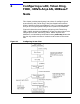
Configuring a LAN, Token Ring, FDDI, 100VG-AnyLAN, 100Base-T Node
To Configure a LAN Network Interface
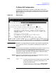
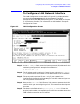
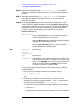
Step 6. Tab down to the field called Enable Ethernet (Y/N). By default,
ethernet is enabled. Change the field to N if you do not want ethernet
enabled.
Step 7. Tab down to field called Enable IEEE 802.3 (Y/N). By default,
IEEE 802.3 is enabled. Change the field to N if you do not want
IEEE 802.3 enabled.
Step 8. Press the
[Save Data] key to save the LAN link configuration. If you
need to identify neighbor gateways, press the
[Neighbor Gateways] key
and proceed to the section in this chapter called “To Identify Neighbor
Gateways.” Otherwise, proceed to Chapter 10, “Validating Network
Transport and Cross-Validating with SYSGEN,” and press the
[Validate Netxport] key.
Optional Keys
Press the
[List NIs] key to list the names and types of
already configured network interfaces.
Press the [Delete NI] key to remove a configured network
interface from the configuration file.
Press the [Read Other NI] key to call up a previously
configured Network Interface name.
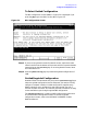
Fields
Node name Display only.
Network
Interface NI)
name Display only.
IP address The IP address is an address of a node on a network. An
IP address has two parts: a network portion and a node
portion. The network portion must be the same for all
nodes on a LAN network; the node portion must be
unique for all nodes on a LAN network.
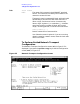
There are two methods of entering an internet protocol (IP) address
within NMMGR:
1. Enter the fully qualified IP address (for example, Class C,
C 192.191.191 009).
OR
2. Enter only the network (nnn) and node (xxx) portions of the IP
address as four positive integers between 0 and 255 separated by
periods or blanks (for example, 15.123.44.98).
You need not enter the following items as NMMGR will fill these in:
• Class A, B, C
• Leading zeros for the network and node portion of the IP address.