
HP e3000/iX Network Planning and Configuration Guide (36922-90037)

46 Chapter3
Planning Your Network
Drawing an Internetwork Map
Network Boundaries
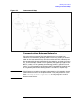
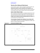
Once you have drawn your gateway nodes or routers, you have
established network boundaries. Consider the example and look at
Figure 3-1. Since node B in the example is a full gateway and belongs to
both NET1 and NET2, the boundary between these two networks is at
node B itself. The boundary between NET2 and NET5 is along the
gateway-half link that connects gateway nodes G and H.
IP Network Addresses
Each network in your internetwork must have a unique IP network
address. Add these IP addresses to your internetwork map.
In the example, assume that the Class C IP network addresses are
those shown in Figure 3-1. The specific IP node addresses do not need to
be shown until completion of specific parts of the network worksheets,
so node portions of IP addresses will be represented with XXX in some
maps and tables.