8-Port Serial PCI ACC Multiplexer Installation and User’s Guide HP e3000 MPE/iX Computer Systems Edition 1 Manufacturing Part Number: 30291-90508 E0201 U.S.A.
Notice The information contained in this document is subject to change without notice. Hewlett-Packard makes no warranty of any kind with regard to this material, including, but not limited to, the implied warranties of merchantability or fitness for a particular purpose. Hewlett-Packard shall not be liable for errors contained herein or for direct, indirect, special, incidental or consequential damages in connection with the furnishing or use of this material.
Contents 1. Overview Multiplexer Overview. . . . . . . . . . . . . . . . . . . . . . . . . . . . . . . . . . . . . . . . . . . . . . . . . . . . . . . . . . 9 Multiplexer Features . . . . . . . . . . . . . . . . . . . . . . . . . . . . . . . . . . . . . . . . . . . . . . . . . . . . . . . . 9 8-Port PCI Multiplexer Maximum Baud Rates . . . . . . . . . . . . . . . . . . . . . . . . . . . . . . . . . . . 10 Multiplexer Architecture . . . . . . . . . . . . . . . . . . . . . . . . . . . . . . . . . . . . . . .
Contents 4
Figures Figure 1-1. Block Diagram of the 8-Port PCI ACC Multiplexer . . . . . . . . . . . . . . . . . . . . . Figure 1-2. HP Z7340A 8-Port PCI ACC Card with Interchange Panels . . . . . . . . . . . . . . Figure 1-3. HP Z7325A Cable Connector (Male) . . . . . . . . . . . . . . . . . . . . . . . . . . . . . . . . . Figure 1-4. HP Z7340A 8-Port PCI ACC Card with Octopus Cable . . . . . . . . . . . . . . . . . . Figure 1-5. Z7321A RS-232 Interchange Panel . . . . . . . . . . . . . . . . . . . . . . . . . . . .
Figures 6
Tables Table 1-1. Accessories . . . . . . . . . . . . . . . . . . . . . . . . . . . . . . . . . . . . . . . . . . . . . . . . . . . . . . Table 2-1. MUX Card LED Display Interpretation . . . . . . . . . . . . . . . . . . . . . . . . . . . . . . . Table 3-1. Clock Source Configuration . . . . . . . . . . . . . . . . . . . . . . . . . . . . . . . . . . . . . . . . . Table A-1. Pin Out Chart for Interchange Panels . . . . . . . . . . . . . . . . . . . . . . . . . . . . . . . .
Tables 8
1 Overview Multiplexer Overview The Advanced Communications Controller (ACC) Subsystem is an intelligent serial communication product for HP e3000 Workstations and Servers. It provides a high performance Wide Area Network (WAN) platform for customers who have large synchronous and asynchronous networks. A complete HP ACC subsystem consists of both the multiplexer hardware and ACC software. This manual describes the 8-port PCI ACC Multiplexer hardware.
Overview Multiplexer Overview 8-Port PCI Multiplexer Maximum Baud Rates Although the ACC MUX card can handle rates above 19.2 Kbps for RS-232 and 64 Kbps for V.35, it is the customer’s responsibility to ensure that the cable type and length are chosen appropriately. Per Port Aggregate RS-232 128 Kbps V.35 128 kbps RS-232 1024 Kbps V.
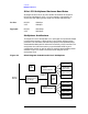
Overview Multiplexer Overview Multiplexer Hardware Requirements The 8-port PCI ACC multiplexer consists of the major hardware components described in Figure 1-2 and shows the components and how they combine to provide the functionality of the ACC subsystem. Figure 1-2 HP Z7340A 8-Port PCI ACC Card with Interchange Panels HP e3000 System with PCI Backplane Interchange Panels 8-port PCI ACC Multiplexer Z7340A Z7325A RS-232 (Z7321A) V.
Overview Multiplexer Overview HP Z7325A MUX/Interchange Panel Cable The MUX connects to the interchange panel by a 160-conductor (28 AWG) cable, three meters (10.77 feet) in length. The cable has male connectors on each end, refer to Figure 1-3. The signals for each of the pins are listed in Appendix A , “Interchange Panels.
Overview Accessories Accessories Table 1-1 lists the accessories available for the 8-port PCI ACC multiplexer. Table 1-1 Accessories Part Number Description Interchange Panels — Each interchange panel product includes the interchange panel, MUX/interchange panel cable, rack-mounting plate, and loopback test kit. Z7321A RS-232 Interchange Panel for PCI ACC Z7322A V.
Overview Interchange Panels Interchange Panels Overview of the Interchange Panels The Multiplexer is designed to connect to an interchange panel, which “breaks out” the signal into the ports. These panels are “passive” distribution panels, accepting the input from the MUX and distributing it to the network. This section describes the various models of interchange panels that are compatible with the 8-port PCI ACC product. Each interchange panel is designed for a specific serial communications standard.
Overview Interchange Panels RS-232 Interchange Panel The RS-232 Interchange Panel is shown in Figure 1-5. Figure 1-5 Z7321A RS-232 Interchange Panel Z7321A RS-232 INTERCHANGE PANEL J7 J6 J5 J4 P2 J3 J2 J1 J0 P1 The signals supported on the RS-232 panels are in Figure 1-6.
Overview Interchange Panels V.35 Interchange Panel The V.35 Interchange Panel is shown in Figure 1-7. Figure 1-7 Z7322A V.35 Interchange Panel Z7322A V.
Overview Interchange Panels The signals supported on the V.35 panels are shown in Figure 1-8. Figure 1-8 Supported V.
Overview Interchange Panels 18 Chapter 1
2 Hardware Installation This chapter describes how to install the 8-port PCI ACC Multiplexer and the interchange panel hardware for HP e3000 Workstations and Servers with a PCI backplane 19
Hardware Installation Unpacking and Handling Unpacking and Handling If evidence of damage is observed when the carton containing the product is opened, inspect all items carefully, keep the shipping carton and packing material for the carrier’s inspection. If any item appears to be damaged, or if the product does not pass verification procedures described in this chapter, notify the nearest HP Sales and Support Office.
Hardware Installation Anti-Static Precautions Anti-Static Precautions Follow these precautions to prevent damage to the multiplexer: • Keep the card in or on its anti-static packaging until you install it, or use a static-free workstation. • Use a grounding wrist strap when handling the interface card to channel static charges safely to ground. • Avoid working on a carpet. Reduce unnecessary movements. These precautions will help prevent static buildup that might damage the card.
Hardware Installation Installing the 8-Port PCI ACC Multiplexer Installing the 8-Port PCI ACC Multiplexer The three major steps to installing the 8-Port PCI ACC Multiplexer are: • Install the MUX card into the HP e3000 computer. • Install the Interchange Panel(s) to the computer’s rack. • Cable the two together. CAUTION The interface cables should be secured to prevent strain to the I/O card connector and panel connectors. The cables are heavy and apply significant force on the connectors.
Hardware Installation Installing the 8-Port PCI ACC Multiplexer 2. Attach the plate to the rack using appropriately-sized machine-metal screws for your rack. 3. Place one interchange panel against the back plane of the mounting plate. Mount it to the plate, using the M3x10 Torx screws provided with the plate. 4. To mount another interchange panel to this same plate, repeat the preceding step. Note that you can position the plate in a different direction from the first one, as shown in Figure 2-2.
Hardware Installation Installing the 8-Port PCI ACC Multiplexer The LED display is listed in Table 2-1. Table 2-1 MUX Card LED Display Interpretation LED Display Meaning LED flashes red for about seven seconds, then flashes green at two-second intervals. This is normal. The MUX card has successfully passed self-test, but the firmware has not been downloaded. LED turns green. The firmware has been successfully downloaded.
Hardware Installation Replacing Interchange Panel(s) Replacing Interchange Panel(s) The following procedure is used for replacing any of the Interchange Panels. Perform this procedure in the order given. CAUTION Before disconnecting and connecting MUX card cables to the interchange panel, be sure that the power to the computer is off. Otherwise, serious equipment damage may occur. Remove the existing panel: 1. Disconnect the I/O cables from the MUX cards to which the panels are linked. 2.
Hardware Installation Storing the 8-Port PCI ACC Multiplexer Storing the 8-Port PCI ACC Multiplexer If this product is to be stored, use the original shipping container, or one of equivalent quality and size. Use anti-static containers for printed circuit assemblies. The storage area should be clean and dry, free of corrosive elements. Ensure that the product will not be dropped or crushed.
Configuration Configuration of Clock Source Using NMMGR 3 Configuration Configuration of Clock Source Using NMMGR Refer to Table 3-1 to configure the clock source parameter using NMMGR: 1. Direct Connect (2 ACC — connected back-to-back using loopback cable). 2. Connected to MODEM (or External DCE device). 3. Direct Connect (ACC and PSI connected back-to-back using loopback cable). NOTE Auto dial is not supported on ACC (outbound Dial is not supported, but inbound connections are supported).
Configuration Configuration of Clock Source Using NMMGR Table 3-1 Clock Source Configuration LOOPBACK Cable End NMMGR Configuration Fields Physical Interface Clock Source Local Mode External 0 (RS-232) 1 (External) 5 (DTE) or 6 (DCE) Internal 0 (RS-232) 0 (Internal) 6 (DCE) or 5 (DTE) External 1 (V.35) 1 (External) 5 (DTE) or 6 (DCE) Internal 1 (V.35) 0 (Internal) 6 (DCE) or 5 (DTE) Connected to Modem N/A 1 (V.
Interchange Panels Interchange Panels, Signals and Pin Assignments A Interchange Panels Interchange Panels, Signals and Pin Assignments Table A-1 shows the Signal pin-out assignments for the interchange panels. All connectors on the interchange panels are female. Table A-1 Pin Out Chart for Interchange Panels Connectors P1, P2 ACC Signal RS-232 Panel V.
Interchange Panels Interchange Panels, Signals and Pin Assignments Table A-1 Pin Out Chart for Interchange Panels Connectors P1, P2 ACC Signal 22 TxDb (J1) 23 RxDa (J1) 24 RxDb (J1) 25 RTSa (J1) 26 RTSb (J1) 27 CTSa (J1) 28 CTSb (J1) 29 DTRa (J1) 30 DTRb (J1) 31 DCDa (J1) 32 DCDb (J1) 33 ETCa (J1) 34 ETCb (J1) 35 RxCa (J1) 36 RxCb (J1) 37 TxCa (J1) 38 TxCb (J1) RS-232 Panel V.
Interchange Panels Interchange Panels, Signals and Pin Assignments Table A-1 Pin Out Chart for Interchange Panels Connectors P1, P2 ACC Signal RS-232 Panel V.
Interchange Panels Interchange Panels, Signals and Pin Assignments Table A-1 Pin Out Chart for Interchange Panels Connectors P1, P2 ACC Signal 82 TxDb (J4) 83 RxDa (J4) 84 RxDb (J4) 85 RTSa (J4) 86 RTSb (J4) 87 CTSa (J4) 88 CTSb (J4) 89 DTRa (J4) 90 DTRb (J4) 91 DCDa (J4) 92 DCDb (J4) 93 ETCa (J4) 94 ETCb (J4) 95 RxCa (J4) 96 RxCb (J4) 97 TxCa (J4) 98 TxCb (J4) 99 SG (J4) 7 B 100 SG (J5) 7 B 101 TxDa (J5) 2 P 102 TxDb (J5) 103 RxDa (J5) 104 RxDb (J5) 10
Interchange Panels Interchange Panels, Signals and Pin Assignments Table A-1 Pin Out Chart for Interchange Panels Connectors P1, P2 ACC Signal 112 DCDb (J5) 113 ETCa (J5) 114 ETCb (J5) 115 RxCa (J5) 116 RxCb (J5) 117 TxCa (J5) 118 TxCb (J5) 119 DUAL OUT 120 DUAL IN 121 TxDa (J6) 122 TxDb (J6) 123 RxDa (J6) 124 RxDb (J6) 125 RTSa (J6) 126 RTSb (J6) 127 CTSa (J6) 128 CTSb (J6) 129 DTRa (J6) 130 DTRb (J6) 131 DCDa (J6) 132 DCDb (J6) 133 ETCa (J6) 134 ETCb (J6) 1
Interchange Panels Interchange Panels, Signals and Pin Assignments Table A-1 Pin Out Chart for Interchange Panels Connectors P1, P2 ACC Signal 142 TxDb (J7) 143 RxDa (J7) 144 RxDb (J7) 145 RTSa (J7) 146 RTSb (J7) 147 CTSa (J7) 148 CTSb (J7) 149 DTRa (J7) 150 DTRb (J7) 151 DCDa (J7) 152 DCDb (J7) 153 ETCa (J7) 154 ETCb (J7) 155 RxCa (J7) 156 RxCb (J7) 157 TxCa (J7) 158 TxCb (J7) RS-232 Panel V.
Interchange Panels RS-232 Loopback RS-232 Loopback The RS-232 loopback cable signals are shown in Figure A-1.
Interchange Panels V.35 Loopback V.35 Loopback The V.35 loopback cable signals are shown in Figure A-2. Figure A-2 V.
B Regulatory/Safety Statements FCC EMI Statement (USA Only) The Federal Communications Commission (in 47 CFR 15.105) has specified that the following notice be brought to the attention of the users of this product. This equipment has been tested and found to comply with the limits for a Class A digital device, pursuant to Part 15 of the FCC Rules. These limits are designed to provide reasonable protection against harmful interference when the equipment is operated in a commercial environment.
Regulatory/Safety Statements Industry Canada EMI Statement Industry Canada EMI Statement This Class A digital apparatus complies with Industry Canada Standard ICES-003. Cet appareil numérique de la classe A est conforme à la norme NMB-003 d’Industrie Canada.
Regulatory/Safety Statements Europe EMI Statement Europe EMI Statement This is a Class A product. In a domestic environment this product may cause radio interference in which case the user may be required to take adequate measures. NOTE Please see Declaration of Conformity statement on following page. Telecommunications Europe This marking is evidence of compliance with the EU Radio Equipment and Telecommunications Terminal Equipment Directive 1999/5/EC and other applicable EU Directives.
Regulatory/Safety Statements Telecommunications Europe DECLARATION OF CONFORMITY according to ISO/IEC Guide 22 and EN 45014 Manufacturer’s name: Hewlett-Packard Company Manufacturer’s address: 19420 Homestead Road Cupertino, California 95014, USA declares that the product: Product Name: PCI 8-Port ACC (Advanced Communications Controller) Model Number(s): Z7340A Product Options: PCI 8-Port Serial Card: Z7340A (HP P/N Z7340-68001) Interchange Panels: Z7321A, Z7322A Cables: Z7325A, Z7326A, Z7327A co