
SNA Link/iX Node Managers Guide (30291-90507)

Chapter 2 35
SNA Node and Link Configuration
Data Required from the Host Configuration
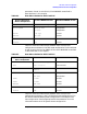
permanent virtual circuits (PVCs). Each NMMGR screen field is
described later in this chapter.
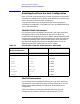
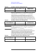
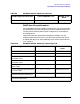
Table 2-3 shows the relationships between items from the host
configuration and items in the SNA node configuration file for switched
virtual circuits (SVCs) of an SNA/X.25 link. Each NMMGR screen field
is described later in this chapter.
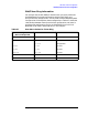
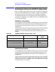
Table 2-4 shows the relationships between items from the host
configuration and items in the X.25 System Access configuration. The
HP SNA Products Remote System Configuration Guide explains the
host configuration. See the appropriate NS documentation for more
information about the X.25 System Access configuration.
Table 2-2 Host Macro Values for X.25 Link PVC
Host Configuration
Macro and Operand
Field in NMMGR Screen SNA Node NMMGR Screen
X25.LINE TYPE Virtual Circuit Type X.25 Link Data
X25.PU PUNAME SNA Node Name Configuration
New Name Configuration
PUTYPE Node Type PU Data
MAXDATA MAX DATA PU Data
X25.LU
LUNAME
LU Name LU Data
LOCADDR LU# LU Data
Table 2-3 Host Macro Values for X.25 Link SVC
Host Configuration
Macro nd Operand
Field in NMMGR Screen SNA Node NMMGR Screen
X25.LINE TYPE Virtual Circuit Type X.25 Link Data
CALL Call Direction X.25 Link Data
PATH DIALNO Remote’s X.25 Network
Address
X.25 Link Data
PU
PUNAME
SNA Node Name Configuration
New Name Configuration
IDBLK ID BLK PU Data
IDNUM ID NUM PU Data
MAXDATA MAX DATA PU Data
LU
LUNAME
LU Name LU Data
LOCADDR LU# LU Data