
HP e3000/iX Network Planning and Configuration Guide (36922-90037)


56 Chapter3
Planning Your Network
Network Worksheets
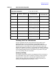
X.25 Network Table
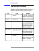
Refer to the X.25 network map to fill in the X.25 network table as
shown in Table 3-6. We complete the first column by listing the names
of all the nodes on NET3. Each node is assigned an IP address that is
unique within the network. Only the node portions of the IP addresses
are listed since the IP network address is listed at the top of the table.
In the third column of the table, node H is indicated as a central
administrative node. The X.25 (subnet) address for each node is listed
in the fifth column of the network table. The X.25 address is a decimal
number (up to 15 digits) identifying a node’s location on the X.25 subnet
for connections using switched virtual circuits (SVCs). Usually this
address is inserted in CALL packets to set up connections using SVCs.
If the network you will access is a public packet switching network
(PSN), these addresses (where appropriate) are recorded on the
network subscription form.
Table 3-6 X.25 Network Table
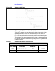
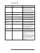
X.25 Internet Routing Table
The purpose of the X.25 internet routing table (Table 3-7) is to list the
other networks in the internetwork that can be reached from the X.25
network, which is NET3 in the example. (Note that there may be more
than one route to a network.)
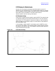
As shown in the internetwork map (Figure 3-4), NET3 includes two
gateway nodes, B and H. In the X.25 internet routing table note that
NET3 nodes using Node H can reach NET5 in one hop, NET2 in two
hops, and so on. In the IP Node Address column, the node portion of the
node’s IP address is listed.
NETWORK NAME: NET3
IP NETWORK ADDRESS C 192.006.251 XXX
NODE NAME IP NODE ADDRESS
CENTRAL ADMIN NODE
(Y/N)
X.25 ADDRESS
H 001 Y 1234
I 002 5678
J 003 6879
B 004 9876