
HP e3000/iX Network Planning and Configuration Guide (36922-90037)


124 Chapter7
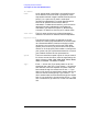
Configuring a Point-to-Point Node
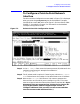
To Configure a Point-to-Point Network Interface
Step 4. Tab down to the Physical Path field. Enter the physical path number
corresponding to the SPU slot number of the programmable serial
interface (PSI) card.
Step 5. Tab to the Speed field. Enter the line transmission speed of this link.
Step 6. Tab to the Type field. Enter DD for direct dial, SD for shared dial or DC
for direct connection.
Step 7. Press the
[Save Data] key to record the data you have entered.
Step 8. If you need to identify neighbor gateways, press the [
Neighbor Gateways]
key and proceed to the section in this chapter called “To Configure
Neighbor Gateways.”
Step 9. If you have already configured neighbor gateways for this link or your
network contains no neighbor gateways, press the
[Link Routing] key
and proceed to the section in this chapter titled “To Configure Node
Mapping.”
Optional Keys
Press the
[List NIs] key to list the names and types of
already configured network interfaces.
Press the [Delete NI] key to remove a configured network
interface from the configuration file.
Press the [Read Other NI] key to call up a previously
configured Network Interface name.
Fields
Node name Display only.
Network
Interface
(NI) name Display only.
IP address The IP address is an address of a node on a network. An
IP address has two parts: a network portion and a node
portion. The network portion must be the same for all
nodes on a LAN network; the node portion must be
unique for all nodes on a LAN network.
There are two methods of entering an internet protocol (IP) address
within NMMGR:
1. Enter the fully qualified IP address (for example, Class C,
C 192.191.191 009).
OR
2. Enter only the network (nnn) and node (xxx) portions of the IP
address as four positive integers between 0 and 255 separated by
periods or blanks (for example, 15.123.44.98).