
Configuring and Managing Host-Based X.25 Links - Edition 6 (36939-90057)

Configuring DTCs Step-by-Step
Modify the Network Management Configuration File
Chapter 3
99
4. Repeat steps 1 to 2 for each local HP e3000 Series 900 system that will be allowed to
establish a PAD connection with local systems. If you need to enter more than eight
local system entries, press the
[Save Data]
key to save the data on this screen, then
use the
[Next Page]
key to move to a new data entry screen to configure additional
systems.
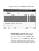
Fields This section contains additional information on the allowed contents of the fields on this
screen.
Maximum number of PAD connections Number of PAD connections that you will allow
at any given time through the card being configured. The maximum
number of connections that can be allowed are:
DTC Type Max Conn Per
X.25 Board
DTC 16 32
DTC48 256
DTC 72MX 256.
NOTE This number specifies the limit for all PAD calls through this card,
including both nailed and non-nailed connections.
Consider the following points when deciding on the maximum number
of SVCs.
• PAD connections use SVCs. The total available number of SVCs is
limited by the number for which you subscribed with the PSN and
configured in the X.25 level 3.
• The same pool of SVCs is used for HP e3000 Series 900
system-to-system switching
• The theoretical maximum of 256 may not be available if you use
the maximum speed of the X.25 board.
If you are configuring system-to-system switching and PAD support on
the same X.25 board, you may need to balance your PAD support
requirements with your system-to-system switching requirements to
find the optimum configuration for your network. If a remote device
attempts to set up a connection and no SVCs are available, the call is
cleared with the message CLR DTE 70 (46 in hexadecimal).
System X.25 Address The X.25 address of the systemnode in this field, up to 15 digits.
For connections to most public data networks, this will be the DTC
X.25 board’s subscription address, plus a unique subaddress for each
system (the full address must be entered for every system).
All nodes must be entered with their full X.25 addresses; you cannot
use X as a replacement of address digits in this box. The remote
terminal user enters this address at the PAD prompt to connect to the
corresponding system.
For one listed system only, you can enter NONE in this field. Incoming
calls with no called address will be routed to this system. If an
incoming call packet has a called address that is not listed, the call is
switched to the DTC user interface.