
Configuring and Managing Host-Based X.25 Links - Edition 6 (36939-90057)

Configuring DTCs Step-by-Step
Modify the Network Management Configuration File
Chapter 3
98
Step 17: Configure PAD Switching
When you press the
[Go to PADswth]
key at the DTC X.25 Card Configuration screen or
the DTC X.25 Card Configuration -- Sys-to-Sys Switch Table screen, NMMGR displays
the DTC X.25 Card Configuration -- PAD Switching Table screen (DTC X.25 Card
Configuration PAD Table Screen). On this screen, you specify information for the PAD
switching table. The PAD Switching table maps the nodenames of LAN-based host
systems to Calling address for PAD devices. The address can be the same or different
from the address you entered for the system in the System to System Switching Table.
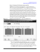
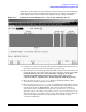
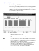
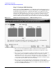
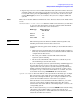
Figure 3-17 DTC X.25 Card Configuration — PAD Switching Screen
1. Move the cursor in the Maximum number of PAD connections field. Enter the
maximum number of simultaneous PAD connection that you will want to allow
through this card.
2. Move the cursor to the System X.25 address field. Enter the same X.25 address as
entered in the X.25 card address field for this node on the System-to-System
Switching table screen, unless your network application requires the address used for
X.25 system-to-system communications to be different from that used for PAD
communications. If the addresses must be different, enter the X.25 address that the
local system will use for PAD connections in this field.
3. Move the cursor to the System Nodenames field. Enter the system nodename
corresponding to the X.25 address. This can be an NS name or an IP address. Use the
reserved name DTC_USER_IF if you want to configure an address that will route
the user to the DTC’s user interface.