
Configuring and Managing Host-Based X.25 Links - Edition 6 (36939-90057)

Configuring DTCs Step-by-Step
Modify the Network Management Configuration File
Chapter 3
88
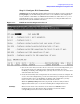
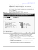
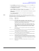
Step 13: Configure X.25 Level 3
NMMGR displays the DTC X.25 Card Configuration — Level 3 screen (Figure 3-13) if
you press the
[Go To Level 3]
key at the DTC X.25 Card Configuration screen or the DTC
X.25 Card Configuration — Level 1 and 2 screen. On this screen, you configure level 3
values for this X.25 card including an X.25 card address. You must configure the level 3
values to enable both system-to-system access and for PAD access. You can also reach
this screen by typing the following path at the Command line and pressing the
[ENTER]
key:
@DTS.DTC.SELECT.dtcname.X25CARDn.LEVEL3
Figure 3-13 DTC X.25 Card Configuration — Level 3 Screen
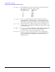
1. Verify that the cursor is in the X.25 card address field. Enter the address that will
be appended to outgoing PAD calls. If no address should be sent in call request
packets, leave this field blank.
2. Use the
[TAB]
key to move to the Logical Channel Identifier
(LCI) Range fields. Enter high and low values for the permanent virtual circuits
(PVCs) or switched virtual circuits (SVCs) you are configuring per your network
subscription. At lease one pair must be configured. Leave the fields blank for
any PVC or SVC types that are not configured.
3. Use the
[TAB]
key to move to the Default Flow Control fields. Enter In and Out
values according to your network subscription.
4. Use the
[TAB]
key to move to the Flow control negotiation field. Enter Y to
enable or N to disable according to your subscription.