
Configuring and Managing Host-Based X.25 Links - Edition 6 (36939-90057)

Configuring DTCs Step-by-Step
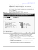
Modify the Network Management Configuration File
Chapter 3
84
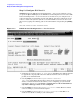
Go to Level 1 & 2 Takes you& to the DTC X.25 Card Configuration — Level 1 and
2 screen. Use this screen to configure level 1 and 2 network
parameters. Most of the information you enter on this screen will
be on the subscription form for the packet switched network you
are connecting to. You must enter level 1 and 2 parameters for all
DTC/X.25 Network Access cards whether they support X.25
system-to-system connections, PAD connections, or both.
Go to Level 3 Takes you to the DTC X.25 Card Configuration — Level 3 screen.
Use this screen to configure level 3 network values. Most of the
information you enter on this screen will be on the subscription
form for the packet switched network you are connecting to. You
must enter level 3 parameters for all DTC/ X.25 Network Access
cards whether they support X.25 system-to-system connections,
PAD connections, or both.
Go to SysLUG Takes you to the DTC X.25 Card Configuration — Sys-to-Sys LUGs
screen. Use this screen to configure the X.25 link name, the
maximum number of switched virtual circuits, and local user group
information the DTC will need in order to support X.25 iX System
Access (NS system-to-system links). Information entered on this
screen must not conflict with information entered during NS link
configuration. (Configure information on this screen only if you are
configuring X.25 system-to-system connections.)
Go to SysSwth Takes you to the DTC X.25 Card Configuration -- Sys-to-Sys
Switching Table Screen. Use this screen to configure the
System-to-System Switching Table. This table maps the incoming
called X.25 addresses to the NS node name of the LAN-based host
system. Information entered on this screen must not conflict with
information entered during NS link configuration. (Configure
information on this screen only if you are configuring X.25
system-to-system connections).
Go to PAD Takes you to the DTC X.25 Card Configuration — Nailed PAD
Connections screen. Use this screen to configure information the
DTC will need in order to support terminals and printers with
permanently assigned ldev numbers (nailed devices) over PAD
connections. (Configure information on this screen only if you are
configuring nailed PAD connections.)
Go to PADSwth Takes you to the DTC X.25 Card Configuration -- PAD Switching
Table screen. The table maps the X.25 called addresses to
LAN-based host systems to allow remote users to access the host
system directly from the PAD prompt by entering the full X.25
address configured in this table. (Configure information on this
screen only if you are configuring PAD connections and want to
allow PAD switching).
Go to Security Takes you to the DTC X.25 Card Configuration — PAD Security
screen. Use this screen to configure security if you want to allow or
disallow PAD access from specific X.25 calling addresses.
(Configure information on this screen only if you are configuring
PAD and want to implement PAD security.)