
Configuring and Managing Host-Based X.25 Links - Edition 6 (36939-90057)

Configuring DTCs Step-by-Step
Modify the Network Management Configuration File
Chapter 3
78
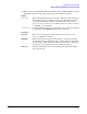
DTC node name The fully qualified node name of the DTC, in the form
nodename.domain.organization. Each part of the name can be up to 16
characters.
DTC IP Address (Optional) The internet protocol (IP) address of the DTC being
configured. An example of an address is: C 192.191.191 009. The IP
address is optional for the DTC, but one must be configured if the DTC
is to be able to respond to PING requests.
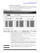
Enable logging class (Y/N) These fields, labeled 1 through 6, enable the DTC to log
various classes of events. Enter a Y to enable a class, N to disable. Only
events falling into classes which you have explicitly enabled will be
logged. Class 1 events are the most critical and will always be logged.
Note that enabling class 5 will result in a substantial number of events
being logged. HP suggests that you enable class 5 only when necessary
and only for short periods of time. You should also avoid enabling
logging class 5 simultaneously with an X.25 trace.
Type (of card) The type of card installed in the DTC. Verify that the cursor is in the
“Type” field under “Enter card types as installed in DTC.”
Enter the card type for each card in the DTC. The valid card types are
listed on the screen.
Enable RAFCP Front End) Enables the DTC to act as a gateway for Routeable AFCP
which is a method of encapsulating AFCP in UDP packets to permit
communications between DTC ports and an HP 3000 Series 900
system across a routed IP network.
Automatic Restart A DTC configuration facility, ensuring the restart of the DTC’s X.25
and PAD Support on the installed SNP boards after a DTC reboot (if
certain conditions have been met).
To configure a card, enter a card number then press Config Card This
parameter determines the next screen that will appear after you have
saved the data configured on the screen. Enter the number of the card
you want to configure and press the
[Config Card]
key.
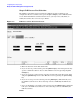
Step10: Configure DTC Cards
When you press the
[Config Card]
key at the DTC Configuration screen, NMMGR will
display the corresponding card configuration screen for the specified card in the DTC.
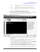
Figure 3-9 shows an example of a Card Configuration screen for DTC 72MX. (Screens
vary slightly for DTC 16iX/16MX/16RX, DTC 16, and DTC 48). Figure 3-10 shows the
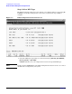
screen for configuring nailed PAD devices on an X.25 card in a non-managed DTC.
NOTE You only need to configure these screen if you want to have nailed ports (such as printer
ports) in the DTC. If you do not want to nailed ports on a card, you can skip this step.
The corresponding screen for a DTC 16iX/16MX/16RX is called a Port Configuration
Screen since DTC 16iX/16MX/16RX has port connectors built directly onto the backplane
and does not have connector cards.
Use this screen to configure the ports in the specified card. On this screen, logical device
(ldev) numbers and profile names are associated with individual ports on the card.