
8-port Serial PCI ACC Multiplexer Installation & Service Guide (30291-90508)


28 Chapter3
Configuration
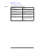
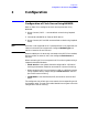
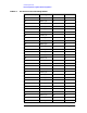
Configuration of Clock Source Using NMMGR
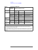
Table 3-1 Clock Source Configuration
LOOPBACK
Cable End NMMGR Configuration Fields
Physical
Interface
Clock Source Local Mode
Direct Connect External 0 (RS-232) 1 (External) 5 (DTE) or 6 (DCE)
Internal 0 (RS-232) 0 (Internal) 6 (DCE) or 5 (DTE)
External 1 (V.35) 1 (External) 5 (DTE) or 6 (DCE)
Internal 1 (V.35) 0 (Internal) 6 (DCE) or 5 (DTE)
Connected to
Modem
N/A 1 (V.35 or
0 (RS-232)
1 (External 6 (DCE) or 5 (DTE)
Direct Connect Internal 0 (RS-232) 0 (Internal) 6 (DCE) or 5 (DTE)
ACC/PSI N/A 1 (V.35) 0 (Internal) 6 (DCE) or 5 (DTE)
Connected to
Modem
N/A 1 (V.25) or
0 (RS-232)
1 (External) 6 (DCE) or 5 (DTE)
Notes:
1. The RS-232 loopback cables are asymmetrical and are labeled “Internal” on one end and
“External” on the other end. The configured clock modes of each port must match the
corresponding end of the loopback cable.
2. The V.35 loopback cables are symmetrical and may be connected either way round. One port
of the pair should be configured for internal (Int) clock and the other to use the (Ext) clock
mode.