HP-PB 100Base-T Network Adapter Installation and Service HP 3000 MPE/iX Computer Systems Edition 1 B5427-90001 E0897 Printed in: U.S.A.
Notice The information contained in this document is subject to change without notice. Hewlett-Packard makes no warranty of any kind with regard to this material, including, but not limited to, the implied warranties of merchantability or fitness for a particular purpose. Hewlett-Packard shall not be liable for errors contained herein or for direct, indirect, special, incidental or consequential damages in connection with the furnishing or use of this material.
Contents HP-PB 100Base-T Network Adapter Installation at a Glance Installation Overview . . . . . . . . . . . . . . . . . . . . . . . . . . . . . . . . . . . . . . . .10 Product Description . . . . . . . . . . . . . . . . . . . . . . . . . . . . . . . . . . . . . . . .10 Product Contents . . . . . . . . . . . . . . . . . . . . . . . . . . . . . . . . . . . . . . . . . .10 Tools and Accessories . . . . . . . . . . . . . . . . . . . . . . . . . . . . . . . . . . . . . . .10 In This Book. . . . . . . . . . .
Contents Removal/Replacement Instructions. . . . . . . . . . . . . . . . . . . . . . . . . . . . . 27 Removal/Replacement of the Adapter . . . . . . . . . . . . . . . . . . . . . . . . . 28 Reshipment Guidelines . . . . . . . . . . . . . . . . . . . . . . . . . . . . . . . . . . . . . . 29 Technical Specifications . . . . . . . . . . . . . . . . . . . . . . . . . . . . . . . . . . . . . . 30 Declaration of Conformity . . . . . . . . . . . . . . . . . . . . . . . . . . . . . . . . . . . .
Figures Figure 1-1 . Address Location . . . . . . . . . . . . . . . . . . . . . . . . . . . . . . . . . .15 Figure 1-2 . Inserting and Securing Adapter . . . . . . . . . . . . . . . . . . . . . .19 Figure 1-3 . Port Connection . . . . . . . . . . . . . . . . . . . . . . . . . . . . . . . . . . .20 Figure 2-1 . Declaration of Conformity. . . . . . . . . . . . . . . . . . . . . . . . . . .
Figures 6
Tables Table 1-1. LED Patterns . . . . . . . . . . . . . . . . . . . . . . . . . . . . . . . . . . . . . .22 Table 2-1. Troubleshooting Checklist . . . . . . . . . . . . . . . . . . . . . . . . . . . .26 Table 2-2. 100Base-T Network Adapter Technical Specifications. . . . . .
Tables 8
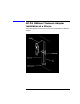
HP-PB 100Base-T Network Adapter Installation at a Glance The following figure shows how to install the HP-PB 100Base-T Network Adapter.
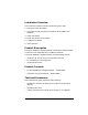
Installation Overview The installation procedure includes the following major steps: 1. Prepare to install the adapter. 2. Shut down the operating system and switch off the power to the computer. 3. Install the adapter. 4. Attach the adapter to the network. 5. Configure the adapter. 6. Verify operation. Product Description The HP-PB 100Base-T Network Adapter provides the hardware needed to interface an HP-PB backplane to a 100Base-T Network.
In This Book This book is the installation and service manual for the HP-PB 100Base-T Network Adapter that connects an HP 3000 computer using the HP-PB backplane to a 100Base-T network. The installation procedure section contains the installation instructions. It explains in detail the steps necessary to install the adapter into your computer. The service information section defines the steps and procedures to follow if you experience trouble with the adapter.
1 Installation Procedure This section contains installation instructions for the HP-PB 100Base-T Network Adapter. The instructions are organized into six primary steps listed below. Each step is described in detail in this section. If the adapter has already been installed at the factory, you may proceed directly to step 4. 1. Prepare to install the adapter. 2. Shut down the operating system and switch off the computer. 3. Install the adapter. 4. Attach the adapter to the network. 5.
Installation Procedure 1. Prepare to Install the Adapter 1. Prepare to Install the Adapter Before installing the adapter, you should perform the following steps: 1. Observe antistatic precautions. 2. Verify product contents. 3. Record adapter identification information. 4. Gather tools and accessories. Observe Antistatic Precautions This product contains electronic components that can easily be damaged by small amounts of static electricity.
Installation Procedure 1. Prepare to Install the Adapter Record Adapter Information Record the relevant information from the card here for future reference. If your adapter requires service in the future this information will be needed by HP service personnel.
Installation Procedure 1. Prepare to Install the Adapter Gather Tools and Accessories Check the hardware installation manual of your computer model for special tools and accessories required to access the I/O adapter slot(s). The following common tools are helpful: • screwdrivers necessary for opening your computer and installing adapters • grounding wrist strap NOTE You should have all of your system and peripheral device manuals available for reference.
Installation Procedure 2. Shut Down the Operating System and Switch Off the Computer 2. Shut Down the Operating System and Switch Off the Computer 1. Before installing the HP-PB 100Base-T Network Adapter, ensure that the operating system is shut down. Refer to your computer system manuals for proper shutdown procedures to avoid corruption or loss of data. 2. Ensure that power to the host computer is switched off and disconnected from the source power supply.
Installation Procedure 3. Install the Adapter 3. Install the Adapter To install the adapter in the host computer, perform the following steps: a. Access the adapter slot(s). b. Select an available adapter slot. c. Insert the adapter into the slot. d. Switch on the power to the computer. a. Access the adapter slot(s) Because computer models vary, there may be different procedures to access and select an adapter slot.
Installation Procedure 3. Install the Adapter 2. Insert the adapter into the slot. Be sure the contacts and adapter guides are properly aligned. 3. Fold in the extractor levers. 4. Press the adapter firmly until you feel the connector mate fully. 5. Secure the adapter in its slot by securing the retaining screws. Figure 1-2 Inserting and Securing Adapter d. Switch on the power to the computer. 1. Reconnect the source power supply to the computer. 2. Switch on the computer power switch.
Installation Procedure 4. Attach the Adapter to the Network 4. Attach the Adapter to the Network Use the RJ-45 connector for connecting a UTP category 5 cable (not supplied) to a 100Base-T or 10Base-T hub/switch. Refer to Figure 1-3. Figure 1-3 Port Connection Attach the cable to the RJ-45 connector by following these steps: a. Plug the cable into the RJ-45 connector. b. Secure the other end of the cable to the 100Base-T or 10Base-T hub/switch. c.
Installation Procedure 5. Configure the Adapter into the System 5. Configure the Adapter into the System On MPE systems you will need to configure the adapter into the system. In particular you must specify link auto-negotiation, speed, and duplex settings to match those of the network hub/switch port to which you attached the adapter.
Installation Procedure 6. Verify Operation 6. Verify Operation Verify proper operation of the HP-PB 100Base-T Network Adapter by checking the LEDs on the card. When the computer is switched on, the Power LED will come on. At this point, the rest of the LEDs are in an uninitialized state, and cannot be used until the driver on the system has been started. After the driver has been started, the following Table 1-1, may be used to interpret the LED patterns.
2 Service Information This section provides the following service information: • Field Replaceable Units • Troubleshooting Tools • Removal/Replacement Instructions • Reshipment Guidelines • Technical Specifications 23
Service Information Field Replaceable Units Field Replaceable Units Field Replaceable Units (FRUs) are assemblies or components that are authorized for field replacement. There are no FRUs on this adapter. If there should be a problem the entire adapter is replaceable. Exchange Assembly The HP-PB 100Base-T Network Adapter may be replaced under the HP board exchange program.
Service Information Troubleshooting Tools Troubleshooting Tools Troubleshooting tools are used to identify faulty adapters. For this product, the following tools are available: • troubleshooting checklist (see Table 2-1) • VGPBA online diagnostic (has online help) Card LEDs The six LEDs on the back of the card can be used to determine the state of the adapter while the driver on the system is running.
Service Information Troubleshooting Tools Table 2-1 Troubleshooting Checklist LED state Power LED off Possible cause Solution No power applied to card Check power to HP-PB bus/system, verify adapter is properly seated in its slot. Blown fuse Replace the adapter Test LED on Driver has detected a fatal hardware or software condition Consult console and/or log files for error messages. Retry the operation. If necessary, contact HP or replace the adapter.
Service Information Removal/Replacement Instructions Removal/Replacement Instructions This section describes removal and replacement for the HP-PB 100Base-T Network Adapter. WARNING Unless otherwise noted in your system manuals, removal of the network adapter should only be done with power removed from the host computer. Failure to comply may result in an electrical shock hazard, or in damage to the hardware. CAUTION The adapter contains electronic components that can be damaged by static electricity.
Service Information Removal/Replacement Instructions Removal/Replacement of the Adapter For adapter removal, follow the procedures below: 1. Before removing the card, ensure that the operating system is shut down and power to the host computer is switched off. Consult your computer documentation for proper shutdown procedures to avoid file corruption or loss of data. 2. Disconnect all cabling from the adapter. 3.
Service Information Reshipment Guidelines Reshipment Guidelines If any item of the product is to be returned to Hewlett-Packard for any reason, contact your HP Sales and Support Office to coordinate the return. When returning the item, attach a tag that identifies the owner and indicates the reason for shipment. Include all relevant information, which includes model, serial, station, and revision numbers. Pack the item in the original factory packaging material if available, or a suitable substitute.
Service Information Technical Specifications Technical Specifications The network adapter technical specifications are provided in Table 2-2. Table 2-2 Specifications 100Base-T Network Adapter Technical Specifications Safety • UL 1950, 2nd Edition • CSA 22.2 No 950, 2nd Edition • IEC 950 (1991)/EN 60950 (1992) Communication Standards • IEEE 802.3u (1995) 100 Mb/s Immunity Standards • ESD: IEC 801-2: 1991 4kV CD, 8 kV AD • IEEE 802.
Service Information Declaration of Conformity Declaration of Conformity A declalaration of conformity is shown in Figure 2-1.
Service Information Declaration of Conformity 32 Chapter 2
Glossary Numbers 10Base-T The name commonly used to refer to the older LAN technology which preceeded 100Base-T. Similar to 100Base-T, but running at 10MBit/s. 100Base-T Also known as Fast Ethernet. Refers to the 100MBit/s network technology over TUP cable that is compatible with the IEEE 802.3u standard. This is a collision-detect technology, i.e., a transmission that collides with another packet already on the LAN, requires retransmitting the new packet.
Glossary E Ethernet A LAN that uses the CSMA/CD method of access and transmits at 10Mbit/s on a bus or star topology. The IEEE 802.3 standard evolved from Ethernet, but they are not exactly the same. Network devices based on both standards can co-exist on the same medium, but they cannot exchange data directly without special “bilingual” software that can decode packets of both types. The drivers for the HP3000 network cards fit this requirement if configured correctly.
Glossary local area network A generalpurpose communications network that interconnects a variety of devices within a limited geographical area. A LAN might connect computers on adjacent desks, within a building, or within several buildings of a campus. information. In the IEEE 802.3 environment this structure is often referred to as the ‘MAC frame”. Packet is the more commonly used term, and originated in the Ethernet environment.
Glossary S T slot The physical place in the back of the computer where a card plugs in. Each slot has a number. token ring A network with a ring topology that uses a token for the purpose of establishing control. Control of the network is passed with the token from one network device to another. star topology A logically starshaped network layout where all traffic is passed through a single point (usually a hub). Hubs can then be connected to form multiple starts.
Index Numerics 100Base-T hub, 20 100Base-T hub/switch, 20 10Base-T hub/switch, 20 A adapter configurations and limitations, 18 adapter part numbers, 24 adapter slot connector, 18 antistatic precautions, 14, 27, 28 attach adapter to network, 20 B backplane, 10 before installing, 14, 17 before removing, 28 C category 3 or 5 cable, 20 configurations and limitations, 18 configure adapter to system, 21 G grounding wrist strap, 10, 14, 16, 27 H HP-PB 100Base-T Network Adapter, 10 HP-PB backplane, 10 hub/switch,