HP A5150A PCI Dual Port Ultra2 SCSI Host Bus Adapter Service and User Guide Edition 2 Customer Order Number: A5150-90001 Manufacturing Part Number: A5150-96002 E0201 U.S.A. © Copyright 2001, Hewlett-Packard Company.
Legal Notices The information in this document is subject to change without notice. Hewlett-Packard makes no warranty of any kind with regard to this manual, including, but not limited to, the implied warranties of merchantability and fitness for a particular purpose. Hewlett-Packard shall not be held liable for errors contained herein or direct, indirect, special, incidental or consequential damages in connection with the furnishing, performance, or use of this material. Warranty.
California. ©copyright 1980, 1984, 1986 Novell, Inc. ©copyright 1986-1992 Sun Microsystems, Inc. ©copyright 1985-86, 1988 Massachusetts Institute of Technology. ©copyright 1989-93 The Open Software Foundation, Inc. ©copyright 1986 Digital Equipment Corporation. ©copyright 1990 Motorola, Inc. ©copyright 1990, 1991, 1992 Cornell University ©copyright 1989-1991 The University of Maryland ©copyright 1988 Carnegie Mellon University Trademark Notices UNIX is a registered trademark of The Open Group.
Contents 1. HP A5150A Adapter Overview About the A5150A Adapter . . . . . . . . . . . . . . . . . . . . . . . . . . . . . . . . . . . . . . . . . . . . . . . . 9 Features . . . . . . . . . . . . . . . . . . . . . . . . . . . . . . . . . . . . . . . . . . . . . . . . . . . . . . . . . . . . . . 10 Interface Descriptions . . . . . . . . . . . . . . . . . . . . . . . . . . . . . . . . . . . . . . . . . . . . . . . . . . . 11 The PCI Interface . . . . . . . . . . . . . . . . . . . . . . . . . . . . . . . . . .
Contents FCC Statement (For U.S.A. Only) . . . . . . . . . . . . . . . . . . . . . . . . . . . . . . . . . . . . . . . . IEC Statement (Worldwide) . . . . . . . . . . . . . . . . . . . . . . . . . . . . . . . . . . . . . . . . . . . . . DOC Statement (Canada). . . . . . . . . . . . . . . . . . . . . . . . . . . . . . . . . . . . . . . . . . . . . . . Spécification ATI Classe A (France . . . . . . . . . . . . . . . . . . . . . . . . . . . . . . . . . . . . . . . VCCI Statement (Japan) . . . . . . . . . . . .
1 HP A5150A Adapter Overview This chapter contains the following sections that describe the HP A5150A PCI Dual Port Ultra2 SCSI host bus adapter (HBA): • “About the A5150A Adapter” on page 9.
HP A5150A Adapter Overview • “Features” on page 10. • “Interface Descriptions” on page 11. • “Supported HP 9000 and HP e3000 Servers” on page 13. • “Cable Specifications” on page 14.
HP A5150A Adapter Overview About the A5150A Adapter About the A5150A Adapter The A5150A Dual Channel PCI Ultra2 SCSI host adapter board provides two SCSI-3 Ultra2 SCSI interfaces to PCI computer systems that require BIOS support on the add-in SCSI adapter. Installing this adapter in your PCI system allows connection of SCSI devices over a SCSI bus.
HP A5150A Adapter Overview Features Features The A5150A adapter has the following features: • PCI interface — Full 32-bit or 64-bit (33 MHz) Direct Memory Access (DMA) bus master. — Zero wait-state bus master data bursts. — PCI Universal 3.3V/5V bus support. • SCSI interface — Two separate SCSI ports. — 16-bit single-ended (SE)/Low Voltage Differential (LVD) — Automatically enabled termination. — 68-pin Very High Density Cable Interconnect (VHDCI) connector for each of the two external channels.
HP A5150A Adapter Overview Interface Descriptions Interface Descriptions This section provides greater detail about the PCI, SCSI, and Wide Ultra2 SCSI interfaces. The PCI Interface PCI is a high-speed standard local bus for interfacing a number of I/O components to a processor and memory subsystem. The PCI functionality for the A5150A is contained within the I/O Processor Chip. The adapter connects directly to the PCI bus and generates timing protocol in compliance with the PCI application.
HP A5150A Adapter Overview Interface Descriptions indicates when the termination power was subjected to an over current condition causing the self-resetting current limiting device (circuit breaker) to trip. A 40 MHz oscillator is installed on the A5150A card to provide the clock frequency necessary to support Wide Ultra2 SCSI transfers of up to 80 MBytes per second. The Wide Ultra2 SCSI Interface The adapter card has full support for Wide Ultra2 SCSI.
HP A5150A Adapter Overview Supported HP 9000 and HP e3000 Servers Supported HP 9000 and HP e3000 Servers Table 1-1 below shows the HP 9000 and HP e3000 servers the A5150A adapter is supported in. Table 1-1 A5150A Supported HP 9000 and HP e3000 Servers HP 9000 Server HP-UX Operating System L-Class 11.0 (or greater) and 11i N-Class 11.0 (or greater) MPE/iX Operating System 7.
HP A5150A Adapter Overview Cable Specifications Cable Specifications The A5150A adapter supports Low Voltage Differential (LVD) or single-ended (SE) connections. Table 1-2 below shows the cables to use when connecting external SCSI peripheral devices to the A5150A adapter. Table 1-2 Cables for Connecting External SCSI Devices to the A5150A Adapter Description Product Number Option 1-meter 68-pin VHDCI to 68-pin HD SCSI cable A3401A 811 2.
2 Installing the A5150A Adapter This chapter contains the following sections that describe how to install the A5150A adapter: • “Preparing for Installation” on page 17.
Installing the A5150A Adapter • “Handling the A5150A Adapter” on page 18. • “Looking at Adapter Installation” on page 19. • “Connecting the SCSI Peripherals” on page 27. • “SCSI Bus Termination” on page 29. • “Verifying Installation” on page 37. NOTE This manual provides installation instructions and technical information for qualified personnel who maintain or service HP 9000 servers. Installing the adapter requires proficiency in both hardware configuration and software administration.
Installing the A5150A Adapter Preparing for Installation Preparing for Installation Installing the host bus adapter requires disassembly of some server components. Before beginning installation, refer to the system server manual for detailed instructions on installing host bus adapters in the PCI slots. You will need the following things: ✓ One HP A5150A SCSI adapter. ✓ One grounding (ESD) strap.
Installing the A5150A Adapter Handling the A5150A Adapter Handling the A5150A Adapter The host bus adapter is packaged with an ESD kit, which contains materials to prevent damage from static electricity during installation. CAUTION The adapter is highly susceptible to damage by electrostatic discharge during installation and routine maintenance procedures. Do not handle circuit boards without wearing a wrist strap fastened to a good earth ground or to the system chassis.
Installing the A5150A Adapter Looking at Adapter Installation Looking at Adapter Installation Installation can be performed in one of two ways: • Use the OLAR (On Line Add/Replace) capability (HP-UX 11i). Refer to “Install Using OLAR (HP-UX 11i)” on page 20. • Power down the system and then add or replace the HBA. Refer to “Install/Replace With System Powered Down” on page 25. The method you choose will depend on your situation, the card you are installing, and your requirements.
Installing the A5150A Adapter Looking at Adapter Installation NOTE The host bus adapter card is supported on the HP N4000 N-class system. Refer to the Hewlett-Packard eproducts web site (http://www.eproducts.hp.com) to disassemble the system, install the adapter in an available PCI slot, and reassemble the system. Install Using OLAR (HP-UX 11i) The letters O, L, A and R stand for On Line Addition [and] Replacement.
Installing the A5150A Adapter Looking at Adapter Installation Table 2-1 IMPORTANT Important Terms Term Meaning OLAR All aspects of the OLAR feature including On-line Addition (OLA) and On-line Replacement (OLR). Power Domain A grouping of 1 or more interface card slots that can be powered on or off as a unit.
Installing the A5150A Adapter Looking at Adapter Installation Planning and Preparation SAM will, generally, prevent you from performing OLAR procedures that would adversely affect other areas of the server. Refer to Configuring HP-UX For Peripherals, HP Part Number B2355-90698 for detailed information. Critical Resources Because power to the slot must be off when the old card is removed and the new card is inserted, the effects of shutting down the card’s functions must be carefully considered.
Installing the A5150A Adapter Looking at Adapter Installation card that operated at a maximum of 33 MHz would not work on a bus running at 66 MHz. rad provides information about the bus frequency and power available at a slot, as well as other slot-related data. On-Line Replacement (OLR) When on-line replacing an interface card, the replacement card must be identical to the card being replaced or at least be able to operate using the same driver as the replaced card.
Installing the A5150A Adapter Looking at Adapter Installation OLA/R Restrictions for the A5150A Currently there are two versions of the A5150A: • A5150-60001 (older) • A5150-60101 (newer) Both of the HBAs have some restrictions in the OLA/R procedure. These restrictions are explained below. Generally, the restrictions are necessary because the SCSI attributes of initiator ID, speed, and auto termination cannot be changed online for this HBA.
Installing the A5150A Adapter Looking at Adapter Installation OLR of A5150-60001 The online replacement operation preserves the initiator ID and speed settings across the replacement. The auto termination setting for this HBA is over-ridden by the jumper settings on the board. Before installation, ensure that the auto termination jumpers are set to the same position as they were on the replaced HBA. Besides the cautions noted above, the A5150-60001 can be Online Replaced without special considerations.
Installing the A5150A Adapter Looking at Adapter Installation CAUTION The adapter is highly susceptible to damage by electrostatic discharge during installation and routine maintenance. Do not handle circuit boards without wearing a wrist strap fastened to a good earth ground or to the system chassis. NOTE A 32-bit slot will work; however, full performance requires a 64-bit slot. Refer to the documentation for your server to confirm the location of the PCI slots.
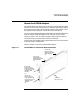
Installing the A5150A Adapter Connecting the SCSI Peripherals Connecting the SCSI Peripherals All external SCSI bus connections to the A5150A host bus adapter are made with shielded, 68-conductor cables. The connectors on this cable are always keyed to ensure proper mating. Some internal cables come with 16bit SE/LVD on one end. This end should be farthest from the host bus adapter.
Installing the A5150A Adapter Connecting the SCSI Peripherals Step 3. If you need to connect more than one external SCSI device to your host bus adapter, chain them together with shielded external SCSI cables. If auto termination has been disabled and you wish to terminate an external connector on the HBA, use HP product number A5296A, VHDCI LVD/SE terminator. Making Internal SCSI Bus Connections Step 1. Identify pin 1 on adapter connector J4 or J5 (internal 68-pin SCSI connector).
Installing the A5150A Adapter SCSI Bus Termination SCSI Bus Termination The devices that make up the SCSI bus are connected serially (chained together) with SCSI cables. The first and last physical SCSI devices connected on the ends of the SCSI bus must have a set of resistors called terminators. All other SCSI devices on the bus must have their terminators removed or disabled. NOTE The A5150A host bus adapter is also on the SCSI bus.
Installing the A5150A Adapter SCSI Bus Termination Table 2-3 Auto Termination PDC Versions HP 9000 System PDC Version A400 and A500 40.20 or later L-Class 39.40 or later N-Class 39.41 or later The A5150A is supported on the A400, A500, L-Class, and N-Class HP 9000 systems. Bus Termination The SCSI bus must be properly terminated. The first and last physical SCSI devices on the ends of the SCSI bus must be terminated either by physical terminators or auto termination.
Installing the A5150A Adapter SCSI Bus Termination In the factory default configuration of the older A5150-60001 HBA, the pin sets are normally open (not shorted together by the jumper). In the open state, the A5150A automatically senses whether a cable from a powered SCSI device is attached, and automatically provides the proper termination (depending on whether a powered device is present or no powered device is present).
Installing the A5150A Adapter SCSI Bus Termination Scenario One If peripheral devices are connected to the external connector and the HBA is at the end of the SCSI bus, you must terminate the last device on the bus. Termination is also required on the HBA. If you have not disabled the auto termination feature of the HBA as described in “How to Turn Off Auto Termination” on page 33, termination is automatically applied on the HBA.
Installing the A5150A Adapter SCSI Bus Termination The HBA is not able to distinguish inline-terminated cables from regular SCSI cables. If an inline-terminated cable is connected to an HBA that has auto termination enabled, termination will be provided by both the cable and the HBA. This would result in improper (double) termination of the SCSI bus. To prevent this, disable auto termination any time inline-terminated cables are connected to the HBA.
Installing the A5150A Adapter SCSI Bus Termination Step 1. Check the PDC version, by booting the system to the BCH prompt and then doing the following: a. At the Main Menu, type in (for Information Menu). b. At the Information Menu, type fv (to display the firmware version). The output could look like this: FIRMWARE INFORMATION Firmware Version: 39.41 Table 2-3, earlier in this document, shows the required PDC versions for using auto termination on each HP 9000 system.
Installing the A5150A Adapter SCSI Bus Termination b. In the Service Menu, type scsi (to display the current status of SCSI devices). The output could look like this: Path (dec) ------------. . 0/2/0/0 Initiator ID ------------ SCSI Rate ------------ Auto Term ------------ 7 Fast Off In this example, the HBA’s auto termination state is Off (shown in bold, for emphasis, in the listing above). c.
Installing the A5150A Adapter SCSI Bus Termination The peripheral device SCSI IDs are usually set with jumpers or a switch on the peripheral. Refer to the peripheral manufacturer’s instructions to determine the ID of each device and how to change it (via BCH for N-Class systems). You must have no duplication of SCSI IDs on a SCSI bus. Step 1. Determine the SCSI ID required for each device on the SCSI bus. Step 2. Make any necessary changes to the SCSI IDs and record the IDs for future reference.
Installing the A5150A Adapter Verifying Installation Verifying Installation After installing the adapter and attaching peripheral devices, verify that all components are working. Refer to your system documentation for information on verifying operation. HP 9000 Step 1.
Installing the A5150A Adapter Verifying Installation HP e3000 Assume an N-Class system with an I/O card being added to slot #12, we will expect paths 1/0/0/0 and 1/0/0/1 to be returned for our card. Step 1. From BCH menus: ------------------------------------------------------Command ------ALL ... IO ...
3 Troubleshooting The A5150A adapter is a single field-replaceable unit (FRU) and does not contain any field-serviceable parts. Troubleshooting procedures described in this chapter are limited to verifying that the adapter is operational and that a valid connection is established.
Troubleshooting This chapter contains the following sections that describe how to troubleshoot the A5150A adapter: • “General Procedure” on page 41. • “Checking SCSI Bus Compatibility” on page 42. • “Using Support Tools Manager (STM)” on page 47. • “Contacting Your Hewlett-Packard Representative” on page 48.
Troubleshooting General Procedure General Procedure The A5150A adapter is a single field-replaceable unit (FRU) and does not contain any field-serviceable parts. Troubleshooting procedures described in this section are limited to verifying that the adapter is operational and a valid connection is established. In general, follow these steps to troubleshoot the A5150A adapter: Step 1. Check the connection.
Troubleshooting Checking SCSI Bus Compatibility Checking SCSI Bus Compatibility You can ensure SCSI controller and SCSI device compatibility by using the SCSI command to display and select SCSI bus parameters. The SCSI command is available from the boot menu displayed after the test station has booted (if autoboot is disabled).
Troubleshooting Checking SCSI Bus Compatibility The SCSI Command As explained above, you can use the SCSI command to check the compatibility of the SCSI adapter and the SCSI device(s), by displaying and setting SCSI bus parameters. Displaying Transfer Rates To use the SCSI command to display the SCSI transfer rate for an adapter, follow this syntax: SCSI rate bus_number slot_number where bus_number Specifies the number of the bus the adapter is installed on.
Troubleshooting Checking SCSI Bus Compatibility Setting Transfer Rates To use the SCSI command to set the SCSI transfer rate for an adapter, follow this syntax: SCSI rate bus_number slot_number rate where bus_number Specifies the number of the bus the adapter is installed on. slot_number Specifies the number of the slot the adapter is in.
Troubleshooting Checking SCSI Bus Compatibility Displaying SCSI IDs To use the SCSI command to display the initiator (SCSI) IDs for an adapter, follow this syntax: SCSI init bus_number slot_number where bus_number Specifies the number of the bus the adapter is installed on. slot_number Specifies the number of the slot the adapter is in. For example: • To display the SCSI ID for the adapter on bus 5 slot 2, issue this command: SCSI init 5 2 The output could look something like this: PCI device /5.
Troubleshooting Checking SCSI Bus Compatibility Setting SCSI IDs To use the SCSI command to set the initiator (SCSI) ID for an adapter, follow this syntax: SCSI init bus_number slot_number ID_number where bus_number Specifies the number of the bus the adapter is installed on. slot_number Specifies the number of the slot the adapter is in. ID_num Specifies the adapter’s SCSI ID number.
Troubleshooting Using Support Tools Manager (STM) Using Support Tools Manager (STM) STM is a software application that can be run from the console to obtain status and descriptive information about the A5150A adapter, diagnose problems, and update firmware. See the Support Tools Manager User’s Guide for more details about STM.
Troubleshooting Contacting Your Hewlett-Packard Representative Contacting Your Hewlett-Packard Representative If the equipment is covered by an HP service contract, document the problem as a service request and forward it to your HP representative. Include the following information where applicable: • Describe the problem, including the events and symptoms leading up to the problem. Attempt to describe the source of the problem.
Troubleshooting Contacting Your Hewlett-Packard Representative which the problem occurs with the circumstances in which the problem does not occur. • In the event of a system failure, obtain a full memory dump. • For HP-UX: If the directory /var/adm/crash exists, the HP-UX utility /sbin/savecore automatically executes during reboot to save the memory dump. HP recommends that you create the /tmp/syscore directory after successfully installing this product.
Troubleshooting Contacting Your Hewlett-Packard Representative 50 Chapter 3
A SCSI Sense Codes This appendix shows the possible codes that appear in SCSI error messages.
SCSI Sense Codes The following example shows a typical SCSI error message: [+6708 72410001 002a9858 0:7] scsi disk: CHECK CONDITION on disk 0:6:5:0 Read of logical block 509856, count 128 disk sd45a, block 254920, 65536 bytes Valid = 1, Error code = 0x70 Segment number = 0x00, Filemark = 0, EOM = 0, ILI = 0 Sense key = 0x1, "RECOVERED ERROR" Information = 0x00 0x07 0xc7 0xe4 [+6709 72410001 002a9a10 0:7] scsi disk: Additional sense length = 0x0a Command-specific information = 0x00 0x00 0x00 0x00 Additional
SCSI Sense Codes Table A-1 below lists all possible SCSI status codes and their meanings.
SCSI Sense Codes Table A-2 below lists all possible SCSI sense keys and their meanings.
SCSI Sense Codes Table A-3 below lists the Additional sense codes and Qualifier codes and their meanings. Remember that you must use the combined codes—an Additional sense code/Qualifier code pair—to find the correct meaning.
SCSI Sense Codes Table A-3 SCSI Additional Sense Code/Qualifier Code Pairs (Continued) SCSI Addition al Sense Code SCSI Qualifier Code Meaning 0x00 Logical unit not ready, cause not reportable 0x01 Logical unit in process of becoming ready 0x02 Logical unit not ready, initializing command required 0x03 Logical unit not ready, manual intervention required 0x04 Logical unit not ready, format in progress 0x05 0x00 Logical unit does not respond to selection 0x06 0x00 Reference position found
SCSI Sense Codes Table A-3 SCSI Additional Sense Code/Qualifier Code Pairs (Continued) SCSI Addition al Sense Code SCSI Qualifier Code Meaning 0x10 0x00 ID crc or ecc error 0x11 0x00 Unrecovered read error 0x01 Read retries exhausted 0x02 Error too long to correct 0x03 Multiple read errors 0x04 Unrecovered read error—auto reallocate failed 0x05 l-ec uncorrectable error 0x06 circ unrecovered error 0x07 Data resynchronization error 0x08 Incomplete block read 0x09 No gap found 0x0a
SCSI Sense Codes Table A-3 SCSI Additional Sense Code/Qualifier Code Pairs (Continued) SCSI Addition al Sense Code SCSI Qualifier Code Meaning 0x00 Recorded entity not found 0x01 Record not found 0x02 Filemark or setmark not found 0x03 End-of-data not found 0x04 Block sequence error 0x00 Random positioning error 0x01 Mechanical positioning error 0x02 Positioning error detected by read of medium 0x16 0x00 Data synchronization mark error 0x17 0x00 Recovered data with no error correct
SCSI Sense Codes Table A-3 SCSI Additional Sense Code/Qualifier Code Pairs (Continued) SCSI Addition al Sense Code SCSI Qualifier Code Meaning 0x00 Recovered data with error correction applied 0x01 Recovered data with error correction and retries applied 0x02 Recovered data—data auto-reallocated 0x03 Recovered data with circ 0x04 Recovered data with lec 0x05 Recovered data—recommend reassignment 0x06 Recovered data—recommend rewrite 0x00 Defect list error 0x01 Defect list not available
SCSI Sense Codes Table A-3 SCSI Additional Sense Code/Qualifier Code Pairs (Continued) SCSI Addition al Sense Code SCSI Qualifier Code Meaning 0x00 Logical block address out of range 0x01 Invalid element address 0x22 0x00 Illegal function 0x24 0x00 Invalid field in cdb 0x25 0x00 Logical unit not supported 0x26 0x00 Invalid field in parameter list 0x01 Parameter not supported 0x02 Parameter value invalid 0x03 Threshold parameters not supported 0x27 0x00 Write protected 0x28 0x0
SCSI Sense Codes Table A-3 SCSI Additional Sense Code/Qualifier Code Pairs (Continued) SCSI Addition al Sense Code SCSI Qualifier Code Meaning 0x2f 0x00 Commands cleared by another initiator 0x30 0x00 Incompatible medium installed 0x01 Cannot read medium—unknown format 0x02 Cannot read medium—incompatible format 0x03 Cleaning cartridge installed 0x31 0x00 Medium format corrupted 0x32 0x00 No defect spare location available 0x01 Defect list update failure 0x33 0x00 Tape length erro
SCSI Sense Codes Table A-3 SCSI Additional Sense Code/Qualifier Code Pairs (Continued) SCSI Addition al Sense Code Meaning SCSI Qualifier Code 0x00 Sequential positioning error 0x01 Tape position error at beginning-of-medium 0x02 Tape position error at end-of-medium 0x03 Tape or electronic vertical forms unit not ready 0x04 Slew failure 0x05 Paper jam 0x06 Failed to sense top-of-form 0x07 Failed to sense bottom-of-form 0x08 Reposition error 0x09 Read past end of medium 0x0a Read pa
SCSI Sense Codes Table A-3 SCSI Additional Sense Code/Qualifier Code Pairs (Continued) SCSI Addition al Sense Code Meaning SCSI Qualifier Code 0x00 Target operation conditions have changed 0x01 Microcode has been changed 0x02 Changed operating definition 0x03 Inquiry data has changed 0x00 RAM failure nn Diagnostic failure on component nn 0x41 0x00 Data path failure 0x42 0x00 Power-on or self-test failure 0x43 0x00 Message error 0x44 0x00 Internal target failure 0x45 0x00 Selec
SCSI Sense Codes Table A-3 SCSI Additional Sense Code/Qualifier Code Pairs (Continued) SCSI Addition al Sense Code SCSI Qualifier Code Meaning 0x00 Write append error 0x01 Write append position error 0x02 Position error related to timing 0x51 0x00 Erase failure 0x52 0x00 Cartridge fault 0x53 0x00 Media load or eject failed 0x01 Unload tape failure 0x02 Medium removal prevented 0x54 0x00 SCSI to host system interface failure 0x55 0x00 System resource failure 0x56 0x00 Reserved
SCSI Sense Codes Table A-3 SCSI Additional Sense Code/Qualifier Code Pairs (Continued) SCSI Addition al Sense Code SCSI Qualifier Code Meaning 0x00 Log exception 0x01 Threshold condition met 0x02 Log counter at maximum 0x03 Log list codes exhausted 0x00 RPL status change 0x01 Spindles synchronized 0x02 Spindles not synchronized 0x5D 0x00 Reserved 0x5E 0x00 Reserved 0x5F 0x00 Reserved 0x60 0x00 Lamp failure 0x61 0x00 Video acquisition error 0x01 Unable to acquire video 0x0
SCSI Sense Codes Table A-3 SCSI Additional Sense Code/Qualifier Code Pairs (Continued) SCSI Addition al Sense Code SCSI Qualifier Code Meaning 0x69 0x00 Reserved 0x6A 0x00 Reserved 0x6B 0x00 Reserved 0x6C 0x00 Reserved 0x6D 0x00 Reserved 0x6E 0x00 Reserved 0x6F 0x00 Reserved 66 Appendix A
B Regulatory Information This appendix contains all of the regulatory-related information for the A5150A adapter.
Regulatory Information Regulatory Statements Regulatory Statements This section contains all of the regulatory statements for the A5150A adapter. FCC Statement (For U.S.A. Only) The Federal Communications Commission (in 47 CFR 15.105) has specified that the following notice be brought to the attention of the users of this product. This equipment has been tested and found to comply with the limits for a Class A digital device, pursuant to Part 15 of the FCC Rules.
Regulatory Information Regulatory Statements Spécification ATI Classe A (France DECLARATION D’INSTALLATION ET DE MISE EN EXPLOITATION d’un matériel de traitement de l’information (ATI), classé A en fonction des niveaux de perturbations radioélectriques émis, définis dans la norme européenne EN 55022 concernant la Compatibilité Electromagnétique.
Regulatory Information Regulatory Statements Declaration of Conformity 70 Appendix B
Glossary A address A specific location in memory, designated either numerically or by a symbolic name. Asynchronous Data Transfer One of the ways data is transferred over the SCSI bus. It is slower than synchronous data transfer. BIOS (Basic Input/Output System) Software that provides basic read/write capability. Usually kept as firmware (ROM based). The system BIOS on the main board of a computer is used to boot and control the system.
flow of data to and from system memory by blocks, as opposed to PIO (Programmed I/O) where the flow is byte by byte. device driver A program that allows a microprocessor (through the operating system) to direct the operation of a peripheral device. differential A hardware configuration for connecting SCSI devices. It uses a pair of lines for each signal transfer (as opposed to single-ended SCSI which references each SCSI signal to a common ground). FCC Federal Communications Commission.
for each SCSI host adapter. ISA (Industry Standard Architecture) A type of computer bus used in most PCs. It allows devices to send and receive data 16 bits at a time. KByte (kilobyte) A measure of computer storage equal to 1024 bytes. local bus A way to connect peripherals directly to the computer processor’s data path. It bypasses the slower ISA and EISA buses. PCI is a local bus standard. logical unit A subdivision, either logical or physical, of a SCSI device.
parity checking A way to verify the accuracy of data transmitted over the SCSI bus. One bit in the transfer is used to make the sum of all the 1 bits either odd or even (for odd or even parity). If the sum is not correct, an error message appears. SCSI uses odd parity. PCI (peripheral component interconnect) A local bus specification that allows connection of integrated peripheral controller components, peripheral add-in boards, and processor/memory systems. It bypasses the slower ISA and EISA busses.
SCSI (small computer system interface) A specification for a high-performance peripheral bus and command set. The original standard is now referred to as SCSI-1. SCSI-2 The current SCSI specification that adds features to the original SCSI-1 standard. SCSI-3 The next SCSI specification, that adds features to the SCSI-2 standard. SDMS (SCSI Device Management System) A Symbios software product that manages SCSI system I/O. single-ended SCSI A hardware specification for connecting SCSI devices.
rate of up to 40 MBytes/sec over an 8-bit SCSI bus, and up to 80 MBytes/sec over a 16-bit SCSI bus. STA (SCSI Trade Association) supports using the term “Ultra2 SCSI” over the older term “Fast-40.” VCCI Voluntary Control Council for Interference. VHDCI Very High Density Cable Interconnect. Wide SCSI A SCSI-2 feature allowing 16 or 32-bit transfers on the SCSI bus. This dramatically increases the transfer rate over the standard 8-bit SCSI bus.