
APPC Subsystem on MPE/XL Node Manager's Guide (30294-90007)

Chapter 4 105
APPC Subsystem Configuration
Configuration Illustrations
Configuration Illustrations
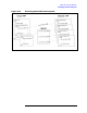
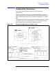
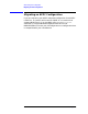
This section contains network diagrams for three example
configurations.
The first illustration, Figure 4-17, shows one dependent LU session
type. The three screens pictured at the bottom of the illustration are the
APPC configuration screens used to configure a dependent LU session
type.
The dashed lines show the correspondence between configuration items
and software entities in the SNA network. The dotted lines show the
APPC sessions that are activated at subsystem startup.
Figure 4-17 Example Configuration, One Session Type