
StorageWorks Modular Smart Array 500 System Maintenance and Service Guide

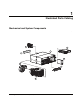
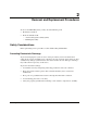
Table Of Contents
- HP StorageWorks Modular Smart Array 500 System Maintenance and Service Guide
- Notice
- Contents
- About This Guide
- Chapter 1: Illustrated Parts Catalog
- Chapter 2: Removal and Replacement Procedures
- Safety Considerations
- System Power Down
- Hard Drive Blank
- Hot-Plug SCSI Hard Drive
- Universal Hot-Plug Tape Drive
- Bezel Blank
- HP StorageWorks Modular Smart Array 500 Controller
- Battery-Backed Cache Module
- Blower
- Hot-Plug Power Supply
- 2-Port and 4-Port Shared Storage Modules
- Interconnect Blank
- Power Button/LED Assembly
- MSA500 System Chassis and Backplane
- Chapter 3: Diagnostic Tools
- Chapter 4: Component Identification
- Front Panel Components
- Enclosure LEDs
- Rear Panel Components
- Power Supply/Blower Assembly LEDs
- 2-Port Shared Storage Module Components
- 2-Port Shared Storage Module LEDs
- 4-Port Shared Storage Module Components
- 4-Port Shared Storage Module LEDs
- Controller Components
- SCSI IDs
- Hot-Plug SCSI Hard Drive LEDs
- Hot-Plug SCSI Hard Drive LED Combinations
- Chapter 5: Specifications
- Index
HP StorageWorks Modular Smart Array 500 System Maintenance and Service Guide v
About This Guide
This maintenance and service guide can be used for reference when servicing the HP
StorageWorks Modular Smart Array 500 system.
WARNING: To reduce the risk of personal injury from electric shock and hazardous
energy levels, only authorized service technicians should attempt to repair this
equipment. Improper repairs can create conditions that are hazardous.
Audience Assumptions
This guide is for service technicians. HP assumes you are qualified in the servicing of
computer equipment and trained in recognizing hazard in products with hazardous energy
levels and are familiar with weight and stability precautions for rack installations.
Technician Notes
WARNING: Only authorized technicians trained by HP should attempt to repair this
equipment. All troubleshooting and repair procedures are detailed to allow only
subassembly/module-level repair. Because of the complexity of the individual boards
and subassemblies, no one should attempt to make repairs at the component level or
to make modifications to any printed wiring board. Improper repairs can create a safety
hazard.
WARNING: To reduce the risk of personal injury from electric shock and hazardous
energy levels, do not exceed the level of repairs specified in these procedures.
Because of the complexity of the individual boards and subassemblies, do not attempt
to make repairs at the component level or to make modifications to any printed wiring
board. Improper repairs can create conditions that are hazardous.
WARNING: To reduce the risk of electric shock or damage to the equipment:
• Disconnect power from the system by unplugging all power cords from the power
supplies.
• Do not disable the power cord grounding plug. The grounding plug is an important
safety feature.
• Plug the power cord into a grounded (earthed) electrical outlet that is easily
accessible at all times.