
StorageWorks Modular Smart Array 500 System Maintenance and Service Guide
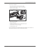
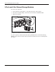
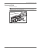
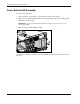
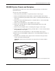
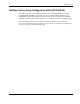
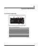
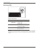
Table Of Contents
- HP StorageWorks Modular Smart Array 500 System Maintenance and Service Guide
- Notice
- Contents
- About This Guide
- Chapter 1: Illustrated Parts Catalog
- Chapter 2: Removal and Replacement Procedures
- Safety Considerations
- System Power Down
- Hard Drive Blank
- Hot-Plug SCSI Hard Drive
- Universal Hot-Plug Tape Drive
- Bezel Blank
- HP StorageWorks Modular Smart Array 500 Controller
- Battery-Backed Cache Module
- Blower
- Hot-Plug Power Supply
- 2-Port and 4-Port Shared Storage Modules
- Interconnect Blank
- Power Button/LED Assembly
- MSA500 System Chassis and Backplane
- Chapter 3: Diagnostic Tools
- Chapter 4: Component Identification
- Front Panel Components
- Enclosure LEDs
- Rear Panel Components
- Power Supply/Blower Assembly LEDs
- 2-Port Shared Storage Module Components
- 2-Port Shared Storage Module LEDs
- 4-Port Shared Storage Module Components
- 4-Port Shared Storage Module LEDs
- Controller Components
- SCSI IDs
- Hot-Plug SCSI Hard Drive LEDs
- Hot-Plug SCSI Hard Drive LED Combinations
- Chapter 5: Specifications
- Index
Component Identification
4-2 HP StorageWorks Modular Smart Array 500 System Maintenance and Service Guide
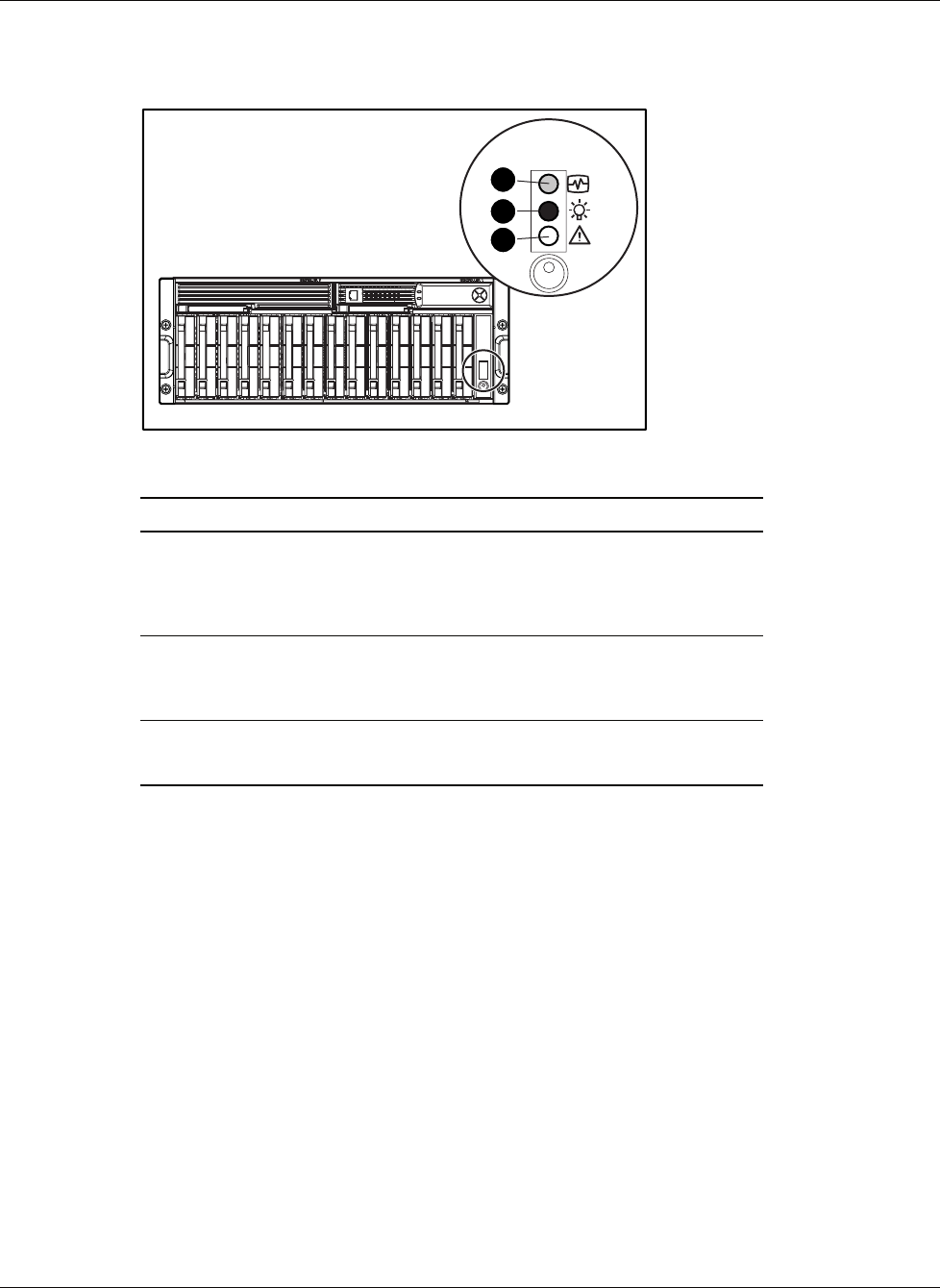
Enclosure LEDs
1
2
3
Table 4-2: Enclosure LEDs
Item LED Description Status
1 Environmental
Monitoring Unit
(EMU) heartbeat
Green flashing = Shared storage module is
operating normally.
Green/Off = Shared storage module is not
operating normally.
2 System power Green = System power is On.
Off = System is in standby mode or power
is removed from the system.
3 Fault Amber = Fault detected in a subsystem
Off = No faults detected
IMPORTANT: The Power On/Standby button does not remove all power from the system. The Standby
mode removes power from most of the electronics and the drives, but portions of the power supply and
some internal circuitry remain active. To remove power completely, disconnect all power cords from the
equipment.