
StorageWorks Modular Smart Array 500 System Maintenance and Service Guide
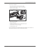
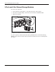
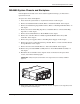
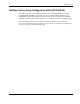
Table Of Contents
- HP StorageWorks Modular Smart Array 500 System Maintenance and Service Guide
- Notice
- Contents
- About This Guide
- Chapter 1: Illustrated Parts Catalog
- Chapter 2: Removal and Replacement Procedures
- Safety Considerations
- System Power Down
- Hard Drive Blank
- Hot-Plug SCSI Hard Drive
- Universal Hot-Plug Tape Drive
- Bezel Blank
- HP StorageWorks Modular Smart Array 500 Controller
- Battery-Backed Cache Module
- Blower
- Hot-Plug Power Supply
- 2-Port and 4-Port Shared Storage Modules
- Interconnect Blank
- Power Button/LED Assembly
- MSA500 System Chassis and Backplane
- Chapter 3: Diagnostic Tools
- Chapter 4: Component Identification
- Front Panel Components
- Enclosure LEDs
- Rear Panel Components
- Power Supply/Blower Assembly LEDs
- 2-Port Shared Storage Module Components
- 2-Port Shared Storage Module LEDs
- 4-Port Shared Storage Module Components
- 4-Port Shared Storage Module LEDs
- Controller Components
- SCSI IDs
- Hot-Plug SCSI Hard Drive LEDs
- Hot-Plug SCSI Hard Drive LED Combinations
- Chapter 5: Specifications
- Index
Removal and Replacement Procedures
HP StorageWorks Modular Smart Array 500 System Maintenance and Service Guide 2-17
MSA500 System Chassis and Backplane
If the backplane board fails or the chassis sustains significant damage, you must order a
replacement chassis.
To replace the chassis and backplane:
1. Power down the system. Refer to “System Power Down” in this chapter.
2. Remove all installed hard drive blanks. Refer to “Hard Drive Blank” in this chapter.
3. Remove all installed hot-plug SCSI hard drives. Refer to “Hot-Plug SCSI Hard Drive” in
this chapter.
4. Remove the Universal Hot-Plug Tape drive, if installed. Refer to “Universal Hot-Plug
Tape Drive” in this chapter.
5. Remove the bezel blank. Refer to “Bezel Blank” in this chapter.
6. Remove the controllers. Refer to “HP StorageWorks Modular Smart Array 500
Controller” in this chapter.
7. Remove the power supplies. Refer to “Hot-Plug Power Supply” in this chapter.
8. Remove the 2-Port or 4-Port Shared Storage module. Refer to “2-Port and 4-Port Shared
Storage Modules” in this chapter.
9. Remove the interconnect blanks. Refer to “Interconnect Blank” in this chapter.
10. Remove the power button/LED assembly. Refer to “Power Button/LED Assembly” in
this chapter.
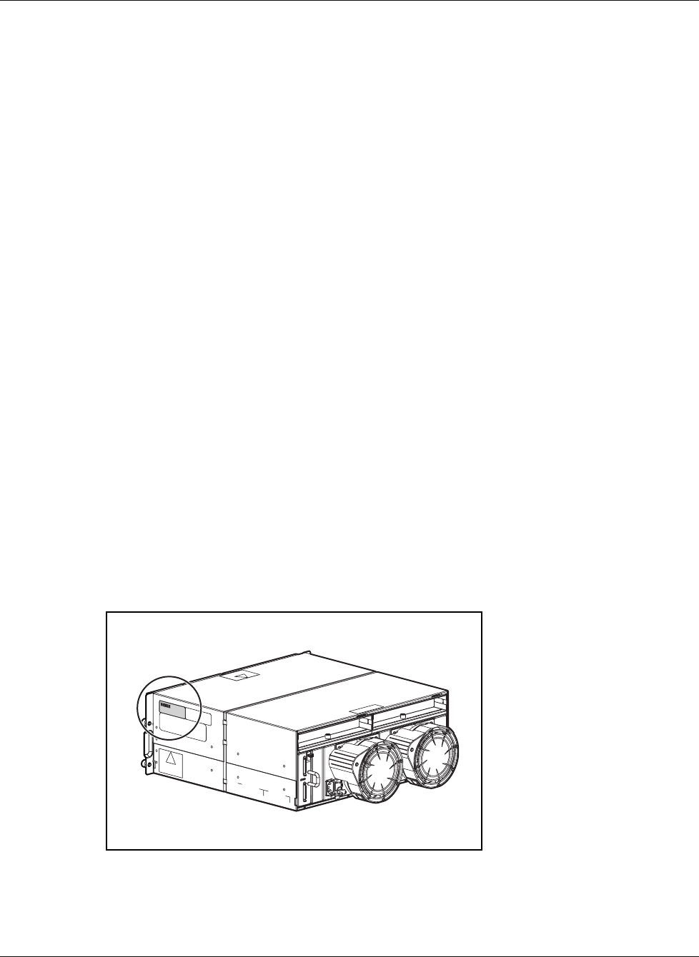
11. Handwrite the serial number of the original chassis on the label on the replacement
chassis, shown in the following figure.
IMPORTANT: Always keep the serial number of the original chassis for warranty validation
purposes.
12. Install all the removed components in the new chassis. To replace each component, refer
to the procedures in this chapter.