
StorageWorks Modular Smart Array 500 System Maintenance and Service Guide
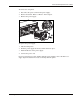
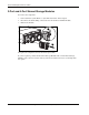
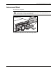
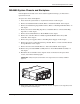
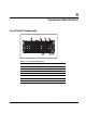
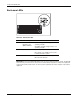
Table Of Contents
- HP StorageWorks Modular Smart Array 500 System Maintenance and Service Guide
- Notice
- Contents
- About This Guide
- Chapter 1: Illustrated Parts Catalog
- Chapter 2: Removal and Replacement Procedures
- Safety Considerations
- System Power Down
- Hard Drive Blank
- Hot-Plug SCSI Hard Drive
- Universal Hot-Plug Tape Drive
- Bezel Blank
- HP StorageWorks Modular Smart Array 500 Controller
- Battery-Backed Cache Module
- Blower
- Hot-Plug Power Supply
- 2-Port and 4-Port Shared Storage Modules
- Interconnect Blank
- Power Button/LED Assembly
- MSA500 System Chassis and Backplane
- Chapter 3: Diagnostic Tools
- Chapter 4: Component Identification
- Front Panel Components
- Enclosure LEDs
- Rear Panel Components
- Power Supply/Blower Assembly LEDs
- 2-Port Shared Storage Module Components
- 2-Port Shared Storage Module LEDs
- 4-Port Shared Storage Module Components
- 4-Port Shared Storage Module LEDs
- Controller Components
- SCSI IDs
- Hot-Plug SCSI Hard Drive LEDs
- Hot-Plug SCSI Hard Drive LED Combinations
- Chapter 5: Specifications
- Index
Removal and Replacement Procedures
2-16 HP StorageWorks Modular Smart Array 500 System Maintenance and Service Guide
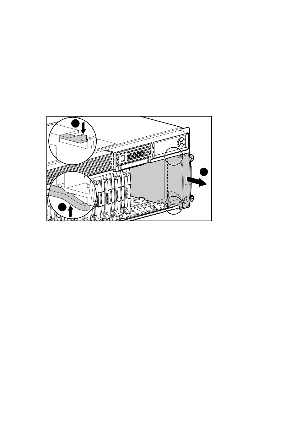
Power Button/LED Assembly
To remove the component:
1. Power down the system. Refer to “System Power Down” in this chapter.
2. Remove the hot-plug SCSI hard drives in bays 10 through 14. Refer to “Hot-Plug SCSI
Hard Drive” in this chapter.
IMPORTANT: To press the plastic latches behind the front bezel, you may choose to use a
flat-head screwdriver.
3. Remove the power button/LED assembly:
2
1
1
To replace the component, slide the power button/LED assembly into the bay until it locks
into place.