
StorageWorks Modular Smart Array 500 System Maintenance and Service Guide
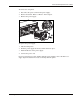
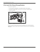
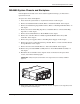
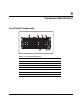
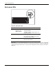
Table Of Contents
- HP StorageWorks Modular Smart Array 500 System Maintenance and Service Guide
- Notice
- Contents
- About This Guide
- Chapter 1: Illustrated Parts Catalog
- Chapter 2: Removal and Replacement Procedures
- Safety Considerations
- System Power Down
- Hard Drive Blank
- Hot-Plug SCSI Hard Drive
- Universal Hot-Plug Tape Drive
- Bezel Blank
- HP StorageWorks Modular Smart Array 500 Controller
- Battery-Backed Cache Module
- Blower
- Hot-Plug Power Supply
- 2-Port and 4-Port Shared Storage Modules
- Interconnect Blank
- Power Button/LED Assembly
- MSA500 System Chassis and Backplane
- Chapter 3: Diagnostic Tools
- Chapter 4: Component Identification
- Front Panel Components
- Enclosure LEDs
- Rear Panel Components
- Power Supply/Blower Assembly LEDs
- 2-Port Shared Storage Module Components
- 2-Port Shared Storage Module LEDs
- 4-Port Shared Storage Module Components
- 4-Port Shared Storage Module LEDs
- Controller Components
- SCSI IDs
- Hot-Plug SCSI Hard Drive LEDs
- Hot-Plug SCSI Hard Drive LED Combinations
- Chapter 5: Specifications
- Index
Removal and Replacement Procedures
HP StorageWorks Modular Smart Array 500 System Maintenance and Service Guide 2-13
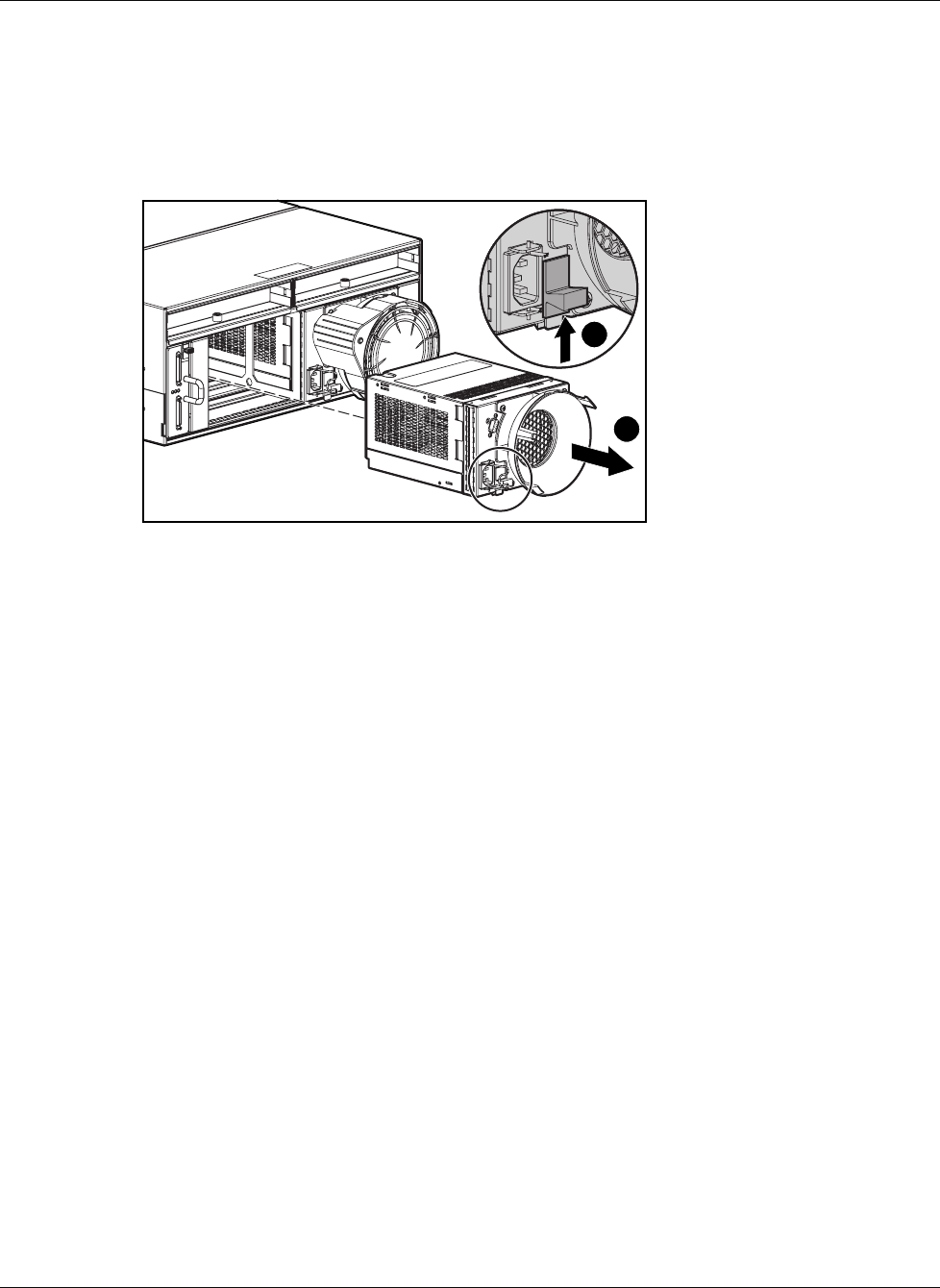
To remove the component:
1. Disconnect the power cord from the power supply.
2. Remove the blower. Refer to “Blower” in this chapter.
3. Remove the power supply.
2
1
To replace the power supply:
1. Lift the locking latch.
2. Slide the power supply into the bay until it locks into place.
3. Install the blower on the power supply.
4. Connect the power cord.
If you are replacing AC power supplies with DC power supplies, refer to the DC Power
Supply Option Installation Instructions that ship with the option.