Internal Cabling Guide for HP Smart Array Controllers First Edition Manufacturing Part Number: 5971-4298 April 2006 © Copyright 2006 Hewlett-Packard Development Company, L.P. All rights reserved.
Legal Notices © 2006 Hewlett-Packard Development Company, L.P. Hewlett-Packard Company shall not be liable for technical or editorial errors or omissions contained herein. The information in this document is provided “as is” without warranty of any kind and is subject to change without notice. The warranties for HP products are set forth in the express limited warranty statements accompanying such products. Nothing herein should be construed as constituting an additional warranty.
Contents 1. Cabling for the HP Integrity rx8620 Server HP Smart Array Controller Card Ports . . . . . . . . . . . . . . . . . . . . . . . . . . . . . . . . . . . . . . . . . . . . . . . . . . . 2 Installing the HP Smart Array Controller Card . . . . . . . . . . . . . . . . . . . . . . . . . . . . . . . . . . . . . . . . . . . . 2 Single Partition RAID Configuration . . . . . . . . . . . . . . . . . . . . . . . . . . . . . . . . . . . . . . . . . . . . . . . . . . . . .
Contents Configuring the Server Firmware and Software for RAID . . . . . . . . . . . . . . . . . . . . . . . . . . . . . . . . . . . 56 6. Cabling for the HP Integrity rx5670 Server Installing the HP Smart Array 5302 or 5304 Controller Card . . . . . . . . . . . . . . . . . . . . . . . . . . . . . . . . Recabling for RAID . . . . . . . . . . . . . . . . . . . . . . . . . . . . . . . . . . . . . . . . . . . . . . . . . . . . . . . . . . . . . . . . . . Setting Up RAID on Hot Plug Drives A and B . . . . . .
1 Cabling for the HP Integrity rx8620 Server This chapter describes how to connect the cables of an HP Smart Array controller card to the internal hard drives of an HP Integrity rx8620 Server. NOTE These instructions do not apply if you are connecting the controller card to an external mass storage box. Refer instead to the HP Smart Array Controller User Guide that shipped with your card.
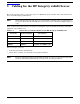
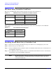
Cabling for the HP Integrity rx8620 Server HP Smart Array Controller Card Ports HP Smart Array Controller Card Ports The ports on the HP Smart Array Controller Cards are labeled as shown in Table 1-2 Table 1-2 HP Smart Array Controller Card Port Labels Controller Card SA 5302/SA5304 SA 6402/SA6404 Port Location Port 1 Port near bulkhead Port 2 Port near center of card Port A2 Port near bulkhead Port A1 Port near center of card When a port is referenced in this document the following notation
Cabling for the HP Integrity rx8620 Server Single Partition RAID Configuration Single Partition RAID Configuration Figure 1-1 shows the correct cabling for a single partition configuration, as viewed from the front of the server.
Cabling for the HP Integrity rx8620 Server Single Partition RAID Configuration RAID Cabling for IO Chassis 0 (Top Left and Top Right Hot Plug Hard Drives) To set up the RAID cabling on the top left and top right hot plug hard drives, do the following: Step 1. Verify that the HP Smart Array controller card is installed in PCI slot 8 of the IO Chassis 0. Step 2. Retrieve two cables from the cable kit (A7027-63001). Step 3.
Cabling for the HP Integrity rx8620 Server Single Partition RAID Configuration Step 9. Unplug the existing SCSI ribbon cable for the top right HDD. This is the second connector from the right on the Mass Storage Bacplane when viewed from the front of the server. See Figure 1-3 Step 10. Fold the SCSI connector on the ribbon cable so it will lay in front of the connector on the Mass Storage Backplane. See Figure 1-2. Step 11.
Cabling for the HP Integrity rx8620 Server Dual Partition Configurations Dual Partition Configurations Figure 1-4 shows the correct cabling for a dual partition configuration, as viewed from the front of the server.
Cabling for the HP Integrity rx8620 Server Dual Partition Configurations WARNING The cables must be routed along the side of the server. They must not lay on top of the flat SCSI ribbon cable bundle or the PCI air dam. Doing so will damage the cables when the top is installed. Step 6. Unplug the existing SCSI ribbon cable for the top left HDD. This is the left most connector on the Mass Storage Backplane when viewed from the front of the server. See Figure 1-4 Step 7.
Cabling for the HP Integrity rx8620 Server Dual Partition Configurations NOTE One end of each cable has a pull-tab connected to the SCSI connector which is labeled “This Connector to PCI Card”. This end of the cable connects to the HP Smart Array card. Step 4. Plug the end of one of the cables with the pull-tab into the SCSI connector Port 1/A2 on the Smart Array card. Repeat for SCSI connector Port 2/A1. Step 5.
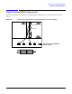
Cabling for the HP Integrity rx8620 Server Dual Partition Configurations Figure 1-6 Smart Array Controller Card with Dual Partition Cabling Removable Media Cable Bundle Ties Port 2/A1 and Bottom Right HDD Cable Connections Chapter 1 PCI Lift Handle Port 1/A2 and Bottom Left HDD Cable Connections 9
Cabling for the HP Integrity rx8620 Server Insight Manager 7 Hard Disk Drive Mapping Insight Manager 7 Hard Disk Drive Mapping The previously described internal drive configuration produces the following mapping in IM7 when events occur on a target HDD, as shown in Table 1-4.
Cabling for the HP Integrity rx8620 Server Configuring the Server Firmware and Software for RAID Configuring the Server Firmware and Software for RAID To complete the installation and set up RAID for your server's internal hot swap drives, follow the procedures given in the Smart Array Controller User Guide: • Configure your HP Smart Array controller card in an HP Integrity server (use HP Smart Array utilities and command line options from the EFI shell) • Install and use the operating system-specific H
Cabling for the HP Integrity rx8620 Server Configuring the Server Firmware and Software for RAID 12 Chapter 1
2 Cabling for the HP Integrity rx8640 Server This chapter describes how to connect the cables of an HP Smart Array controller card to the internal hard drives of an HP Integrity rx8640 Server. These instructions do not apply if you are connecting the controller card to an external mass storage box. Refer instead to the HP Smart Array Controller User Guide that shipped with your card.
Cabling for the HP Integrity rx8640 Server Single Partition RAID Configuration Single Partition RAID Configuration Figure 2-1 shows the correct cabling for a single partition configuration, as viewed from the front of the server.
Cabling for the HP Integrity rx8640 Server Single Partition RAID Configuration RAID Cabling for IO Chassis 0 (Top Left and Top Right Hot Plug Hard Drives) To set up the RAID cabling on the top left and top right hot plug hard drives, do the following: Step 1. Verify that the HP Smart Array controller card is installed in PCI slot 8 of the IO Chassis 0. Step 2. Retrieve two cables from the cable kit (A7027-63001). Step 3.
Cabling for the HP Integrity rx8640 Server Single Partition RAID Configuration Step 9. Unplug the existing SCSI ribbon cable for the top right HDD. This is the second connector from the right on the Mass Storage Bacplane when viewed from the front of the server. See Figure 2-2 Step 10. Fold the SCSI connector on the ribbon cable so it will lay in front of the connector on the Mass Storage Backplane. See Figure 2-2. Step 11.
Cabling for the HP Integrity rx8640 Server Dual Partition Configurations Dual Partition Configurations This section gives instructions for the installation of a second Smart Array Controller Card into the server. This will provide a dual partition configuration in the server. Figure 2-4 shows the correct cabling for a dual partition configuration, as viewed from the front of the server.
Cabling for the HP Integrity rx8640 Server Dual Partition Configurations Step 5. Route the cables as shown in Figure 2-3 towards the front of the server and over to the Mass Storage Backplane connectors. WARNING The cables must be routed along the side of the server. They must not lay on top of the flat SCSI ribbon cable bundle or the PCI air dam. Doing so will damage the cables when the top is installed. Step 6. Unplug the existing SCSI ribbon cable for the top left HDD.
Cabling for the HP Integrity rx8640 Server Dual Partition Configurations Figure 2-6 Smart Array Controller Card with Dual Partition Cabling Removable Media Cable Bundle PCI Lift Handle Ties Port A1 and Top Right HDD Cable Connections Port A2 and Top Left HDD Cable Connections RAID Cabling for IO Chassis 1 (Bottom Left and Bottom Right Hot Plug Hard Drives) To set up the RAID cabling on the bottom left and bottom right hot plug hard drives, do the following, from the front of the server: Step 1.
Cabling for the HP Integrity rx8640 Server Dual Partition Configurations Step 4. Plug the end of one of the cables with the pull-tab into the SCSI connector Port A2 on the Smart Array card (Port 1 is near the rear of the server). Repeat for SCSI connector Port A1 (Port 2 is near the center of the board). Step 5. Route the cables as shown in Figure 2-7 towards the front of the server and over to the Mass Storage Backplane connectors.
Cabling for the HP Integrity rx8640 Server Dual Partition Configurations Figure 2-7 Smart Array Controller Card with Dual Partition Cabling Removable Media Cable Bundle Ties Port A1 and Bottom Right HDD Cable Connections Chapter 2 PCI Lift Handle Port A2 and Bottom Left HDD Cable Connections 21
Cabling for the HP Integrity rx8640 Server Insight Manager 7 Hard Disk Drive Mapping Insight Manager 7 Hard Disk Drive Mapping The previously described internal drive configuration produces the following mapping in IM7 when events occur on a target HDD, as shown in Table 2-2.
Cabling for the HP Integrity rx8640 Server Configuring the Server Firmware and Software for RAID Configuring the Server Firmware and Software for RAID To complete the installation and set up RAID for your server's internal hot swap drives, follow the procedures given in the Smart Array Controller User Guide: • Configure your HP Smart Array controller card in an HP Integrity server (use HP Smart Array utilities and command line options from the EFI shell) • Install and use the operating system-specific H
Cabling for the HP Integrity rx8640 Server Configuring the Server Firmware and Software for RAID 24 Chapter 2
3 Cabling for the Server Expansion Unit This chapter describes how to connect the cables of an HP Smart Array controller card to the internal hard drives of a Server or Server Expansion Unit (SEU) connected to an HP Integrity rx8620 or rx8640 server. NOTE These instructions do not apply if you are connecting the controller card to an external mass storage box. Refer instead to the HP Smart Array Controller User Guide that shipped with your card.
Cabling for the Server Expansion Unit HP Smart Array Controller Card Ports HP Smart Array Controller Card Ports The ports on the HP Smart Array Controller Cards are labeled as shown in Table 3-2 Table 3-2 HP Smart Array Controller Card Port Labels Controller Card SA 5302/SA5304 SA 6402/SA6404 Port Location Port 1 Port near bulkhead Port 2 Port near center of card Port A2 Port near bulkhead Port A1 Port near center of card When a port is referenced in this document the following notation is u
Cabling for the Server Expansion Unit Single Partition RAID Configuration Single Partition RAID Configuration Figure 3-1 shows the correct cabling for a single partition configuration, as viewed from the front of the SEU.
Cabling for the Server Expansion Unit Single Partition RAID Configuration RAID Cabling for IO Chassis 0 (Top Left and Top Right Hot Plug Hard Drives) To set up the RAID cabling on the top left and top right hot plug hard drives, do the following: Step 1. Verify that the HP Smart Array controller card is installed in PCI slot 8 of the IO Chassis 0. Step 2. Retrieve two cables from the cable kit (A7027-63001). Step 3.
Cabling for the Server Expansion Unit Single Partition RAID Configuration Step 9. Unplug the existing SCSI ribbon cable for the top right HDD. This is the second connector from the right on the Mass Storage Bacplane when viewed from the front of the server. See Figure 3-3 Step 10. Fold the SCSI connector on the ribbon cable so it will lay in front of the connector on the Mass Storage Backplane. See Figure 3-2. Step 11.
Cabling for the Server Expansion Unit Dual Partition Configurations Dual Partition Configurations Figure 3-4 shows the correct cabling for a dual partition configuration, as viewed from the front of the SEU.
Cabling for the Server Expansion Unit Dual Partition Configurations WARNING The cables must be routed along the side of the server. They must not lay on top of the flat SCSI ribbon cable bundle or the PCI air dam. Doing so will damage the cables when the top is installed. Step 6. Unplug the existing SCSI ribbon cable for the top left HDD. This is the left most connector on the Mass Storage Backplane when viewed from the front of the server. See Figure 3-1 Step 7.
Cabling for the Server Expansion Unit Dual Partition Configurations NOTE One end of each cable has a pull-tab connected to the SCSI connector which is labeled “This Connector to PCI Card”. This end of the cable connects to the HP Smart Array card. Step 4. Plug the end of one of the cables with the pull-tab into the SCSI connector Port 1A2 on the Smart Array card. Repeat for SCSI connector Port 2/A1. Step 5.
Cabling for the Server Expansion Unit Dual Partition Configurations Figure 3-6 Smart Array Controller Card with Dual Partition Cabling Removable Media Cable Bundle Ties Port 2 and Bottom Right HDD Cable Connections Chapter 3 PCI Lift Handle Port 1 and Bottom Left HDD Cable Connections 33
Cabling for the Server Expansion Unit Insight Manager 7 Hard Disk Drive Mapping Insight Manager 7 Hard Disk Drive Mapping The previously described internal drive configuration produces the following mapping in IM7 when events occur on a target HDD, as shown in Table 3-4.
Cabling for the Server Expansion Unit Configuring the Server Firmware and Software for RAID Configuring the Server Firmware and Software for RAID To complete the installation and set up RAID for your server's internal hot swap drives, follow the procedures given in the Smart Array Controller User Guide: • Configure your HP Smart Array controller card in an HP Integrity server (use HP Smart Array utilities and command line options from the EFI shell) • Install and use the operating system-specific HP Sma
Cabling for the Server Expansion Unit Configuring the Server Firmware and Software for RAID 36 Chapter 3
4 Cabling for the HP Integrity rx7620 Server This chapter describes how to connect the cables of an HP Smart Array 6402 or 6404 controller card to the internal hard drives of an HP Integrity rx7620 Server. These instructions do not apply if you are connecting the controller card to an external mass storage box. Refer instead to the HP Smart Array Controller User Guide that shipped with your card. NOTE The Smart Array 6400 series of controller cards includes two models: the 6402 and the 6404.
Cabling for the HP Integrity rx7620 Server Recabling for RAID Recabling for RAID From the factory, the internal hot plug drives for the HP Integrity rx7620 server are connected to the integrated SCSI card as follows (when viewed from the front of the server): • The top left hard drive has a SCSI connector cabled to the management processor (MP) card • The top right hard drive has a SCSI connector cabled to the Core I/O slot 8 cell 1 • The bottom left and right hard drive has a SCSI connector cabled to
Cabling for the HP Integrity rx7620 Server Recabling for RAID Setting up RAID Cabling for IO Chassis 1 (Top Left and Top Right Hot Plug Hard Drives) To set up the RAID cabling on the top left and top right hot plug hard drives, do the following: Step 1. Verify that the HP Smart Array controller card is installed in PCI slot 1-7. Step 2. Retrieve two cables from the cable kit (A7027-63001). Step 3. Identify the new cables using the colored cable ties which are also contained in the cable kit.
Cabling for the HP Integrity rx7620 Server Recabling for RAID Figure 4-2 Smart Array 6402 Controller Card with Single Partition Cabling Port A2 and Top Left HDD Cabling 40 Port A1 and Top Right HDD Cabling Chapter 4
Cabling for the HP Integrity rx7620 Server Recabling for RAID Dual Partition Configurations Figure 4-3 shows the correct cabling for a dual partition configuration, as viewed from the front of the server. Figure 4-3 Smart Array 6402 or 6404 Controller Card with Dual Partition Cabling Setting up RAID Cabling for IO Chassis 1 (Top Left and Top Right Hot Plug Hard Drives) To set up the RAID cabling on the top left and top right hot plug hard drives, do the following: Step 1.
Cabling for the HP Integrity rx7620 Server Recabling for RAID Step 8. Plug the new cable from the Smart Array card Port A2 (closest to the bracket) into the mass storage connector for the top left drive. See Figure 4-3. Step 9. Plug the new cable from the Smart Array card Port A1 (closest to the center of the board) into the mass storage connector for the top right drive. See Figure 4-3. Step 10. Arrange the new cables so that all of the slack is located in the PCI area. Step 11.
Cabling for the HP Integrity rx7620 Server Recabling for RAID Figure 4-4 Smart Array 6402 or 6404 Controller Card with Dual Partition Cabling Port A2 and Top Left HDD Cabling Port A1 and Bottom HDDs Cabling Port A1 and Top Right HDD Cabling Chapter 4 43
Cabling for the HP Integrity rx7620 Server Insight Manager 7 Hard Disk Drive Mapping Insight Manager 7 Hard Disk Drive Mapping The previously described internal drive configuration produces the following mapping in IM7 when events occur on a target HDD as shown in Table 4-2.
5 Cabling for the HP Integrity rx7640 Server This chapter describes how to connect the cables of an HP Smart Array 6402 or 6404 controller card to the internal hard drives of an HP Integrity rx7640 Server. NOTE These instructions do not apply if you are connecting the controller card to an external mass storage box. Refer instead to the HP Smart Array Controller User Guide that shipped with your card. The Smart Array 6400 series of controller cards includes two models: the 6402 and the 6404.
Cabling for the HP Integrity rx7640 Server Recabling for RAID • The bottom right hard drive has a SCSI connector cabled to Core I/O slot 8 cell 0 LAN SCSI card. To use RAID with your hot plug drives, you must reconfigure the internal SCSI cables as instructed and use the Cable kit (A7027-63001). Follow the instruction below for the configuration you are installing.
Cabling for the HP Integrity rx7640 Server Recabling for RAID Setting up RAID Cabling for IO Chassis 1 (Top Left and Top Right Hot Plug Hard Drives) To set up the RAID cabling on the top left and top right hot plug hard drives, do the following: Step 1. If the server is running, shut down the OS, power off the server, and unplug the power cords. Step 2. Remove the top and left covers of the server. NOTE The HP Smart Array Card must be installed in slot 8 of the rx7640 server.
Cabling for the HP Integrity rx7640 Server Recabling for RAID Step 9. Carefully route the round SCSI cable through the cable guide attached to the system backplane to the front of the server. The cable follows the same path as the flat SCSI ribbon cable already installed in the server. See Figure 5-3. Figure 5-3 SCSI Cable Routed Through Cable Guide Step 10.
Cabling for the HP Integrity rx7640 Server Recabling for RAID Step 18. Arrange the new cable so that all of the slack is located in the PCI area. Step 19. Loop the cable slack and wrap a Kwik Wrap around it to maintain the slack. This allows servicing of the other PCI cards. See Figure 5-5. Figure 5-5 Smart Array 6402 Controller Card with Single Partition Cabling Port A2 and Top Left HDD Cabling using new round SCSI cable Port A1 and Top Right HDD Cabling using integrated flat SCSI cable Step 20.
Cabling for the HP Integrity rx7640 Server Recabling for RAID Dual Partition Configuration Figure 5-1 shows the correct cabling for a dual partition configuration, as viewed from the front of the server.
Cabling for the HP Integrity rx7640 Server Recabling for RAID Setting up RAID Cabling for Dual Partitions To set up the RAID cabling do the following: Step 1. If the server is running, shut down the OS, power off the server, and unplug the power cords. Step 2. Remove the top and left covers of the server. NOTE The HP Smart Array Cards must be installed in slot 8 of the rx7640 server. This requires the LAN/SCSI cards to be moved to slot 7 in the IO chassis.
Cabling for the HP Integrity rx7640 Server Recabling for RAID Figure 5-7 SCSI Cables Routed Through PCI Card Cage Handle Step 12. Carefully route the round SCSI cables through the cable guide attached to the system backplane to the front of the server. The cable follows the same path as the flat SCSI ribbon cable already installed in the server. See Figure 5-8. Figure 5-8 SCSI Cable Routed Through Cable Guide Step 13.
Cabling for the HP Integrity rx7640 Server Recabling for RAID Figure 5-9 Folded SCSI Connector Step 14. Plug a new cable into the mass storage connector for the top left drive. Step 15. Unplug the existing SCSI ribbon cable for the bottom left HDD (disk 3) and fold the SCSI connector on the ribbon cable so it will lay in front of the connector on the Mass Storage Backplane. See Figure 5-6 and Figure 5-9. Step 16. Pull any excess cable into the PCI card cage of the server. Step 17.
Cabling for the HP Integrity rx7640 Server Recabling for RAID Figure 5-10 Smart Array 6402 Controller Card with Dual Partition Cabling Chassis 1 Port A1 and Top Right HDD Cabling Port A2 and Top Left HDD Cabling 54 Chapter 5
Cabling for the HP Integrity rx7640 Server Recabling for RAID Figure 5-11 Smart Array 6402 Controller Card with Dual Partition Cabling Chassis 0 Port A2 and Bottom Left HDD Cabling Port A1 and Bottom Right HDD Cabling Step 28. Reinstall the top and side covers. Step 29. Reinstall the power cords. Step 30. HP Smart Array Controller card installation is complete.
Cabling for the HP Integrity rx7640 Server Insight Manager 7 Hard Disk Drive Mapping Insight Manager 7 Hard Disk Drive Mapping The previously described internal drive configuration produces the following mapping in IM7 when events occur on a target HDD as shown in Table 5-2.
6 Cabling for the HP Integrity rx5670 Server This chapter describes how to connect the cables of an HP Smart Array 5302 or 5304 controller card to the internal hard drives of an HP Integrity rx5670 Server. NOTE These instructions do not apply if you are connecting the controller card to an external mass storage box. Refer instead to the HP Smart Array Controller User Guide that shipped with your card. The Smart Array 5300 series of controller cards includes two models: the 5302 and the 5304.
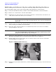
Cabling for the HP Integrity rx5670 Server Figure 6-2 NOTE Smart Array 5304 Controller Card If an HP Server rx5670 is ordered from the factory along with an internal RAID option (with the HP Smart Array controller card and extension cable A9828-63001 pre-installed), this extension cable connects hot plug drives A and B to PORT 1 of the HP Smart Array controller card installed in PCI slot 4. Refer to Figure 6-5 for the PCI slot location and Figure 6-7 for the physical drive location.
Cabling for the HP Integrity rx5670 Server Installing the HP Smart Array 5302 or 5304 Controller Card Installing the HP Smart Array 5302 or 5304 Controller Card Step 1. If the server is running, shut down the OS, power off the server, and unplug the power cord. Step 2. Remove the side cover of the server: a. Loosen the captive T-15 screws that hold the side cover in place. b.
Cabling for the HP Integrity rx5670 Server Installing the HP Smart Array 5302 or 5304 Controller Card Figure 6-4 PCI Card Separator/Extractor 1 Step 4. Install the HP Smart Array 5302 or 5304 controller card in PCI Slot 4 (see Figure 6-5). When finished, you should have the following cards in the server's first four PCI slots: 1. MP/SCSI board located in PCI slot 1 (Item 1 in Figure 6-5) 2. Optional Video board located in PCI slot 2 3. LAN/SCSI board located in PCI slot 3 4.
Cabling for the HP Integrity rx5670 Server Installing the HP Smart Array 5302 or 5304 Controller Card Figure 6-5 PCI Card Order Chapter 6 61
Cabling for the HP Integrity rx5670 Server Recabling for RAID Recabling for RAID From the factory, the internal hot plug drives for the HP rx5670 server are connected to the integrated SCSI as follows (see Figure 6-6 and Figure 6-7): • The MP/SCSI board in PCI slot 1 has a SCSI connector cabled to physical drives A and B • The LAN/SCSI board in PCI slot 3 has a SCSI connector cabled to physical drives C and D Figure 6-6 Default Cabling for Internal SCSI Hot Plug Drives Figure 6-7 Physical Drive Loca
Cabling for the HP Integrity rx5670 Server Recabling for RAID NOTE To connect drives A, B, C, and D, follow all steps in both of the sections described below. Setting Up RAID on Hot Plug Drives A and B Step 1. Confirm the HP Smart Array 5302 or 5304 controller card is installed in PCI slot 4. See “Installing the HP Smart Array 5302 or 5304 Controller Card” on page 59. Step 2. Plug one end of the A9828-63001 cable into the controller card's internal PORT 1 connector.
Cabling for the HP Integrity rx5670 Server Configuring the Server Firmware and Software for RAID Configuring the Server Firmware and Software for RAID To complete the installation and set up RAID for your server's internal hot swap drives, follow the procedures given in the Smart Array 5300 Controller User Guide: • Configure your HP Smart Array 5302 or 5304 controller card in an HP Integrity server (use HP Smart Array 5300 utilities and command line options from the EFI shell) • Install and use the oper
7 Cabling for the HP 9000 rp3440 Server This chapter describes how to connect the cables of an HP Smart Array 6402 or 6404 controller card to the internal hard drives of an HP 9000 rp3440 server. NOTE These instructions do not apply if you are connecting the controller card to an external mass storage box. Refer instead to the HP Smart Array Controller User Guide that shipped with your card. The Smart Array 6400 series of controller cards includes two models: the 6402 and the 6404.
Cabling for the HP 9000 rp3440 Server Figure 7-1 Smart Array 6402 Controller Card (SA 6404 card not shown) Table 7-2 identifies the major components of the Smart Array 6402 controller card.
Cabling for the HP 9000 rp3440 Server Installing the HP Smart Array Controller Card required for RAID, you need to install cable A7231-63025. Refer to “Recabling for RAID” on page 69. If you opt to use both ports of the Smart Array controller card for your internal drives, you must purchase an additional HP Smart Array controller if you want external RAID mass storage. Installing the HP Smart Array Controller Card Step 1.
Cabling for the HP 9000 rp3440 Server Installing the HP Smart Array Controller Card Step 4. Grasp the PCI cage cover and slide it away from the bulkhead end of the PCI cage. Lift the cover off the PCI cage as shown in Figure 7-3. Figure 7-3 Removing the PCI Cage Board Cover Step 5. Install the HP Smart Array controller card in PCI Slot 3 (see Figure 7-4). This is required when connecting the HP Smart Array controller card to the internal hard disk drives.
Cabling for the HP 9000 rp3440 Server Recabling for RAID Recabling for RAID If the HP Smart Array controller card is not pre-installed in your server from the factory, then the rp3440 internal hard drives are connected to the integrated SCSI controller with two internal SCSI cables attached to the system board and the hard drive backplane, as follows: • One of the internal SCSI cables (p/n A7231-63017) connects to the CH A connector of the hard drive backplane, and is then routed and connected to physical
Cabling for the HP 9000 rp3440 Server Recabling for RAID Figure 7-7 Location of Fan 2 and Fan 3 3 Front of server 2 Step 2. To remove a fan, grasp the fan module with your index finger and thumb and lift it out of its slot. Note that each of the modules has indentations for grasping them with your index finger and thumb (see Figure 7-8). Figure 7-8 Removing the Fans Step 3. To remove a SCSI cable, lift up on the fan power bridge as shown in Figure 7-9.
Cabling for the HP 9000 rp3440 Server Recabling for RAID Step 4. Unplug one or both of the SCSI cables connected to the hard drive backplane (see Figure 7-5), depending upon whether you want to use one or both channels of the HP Smart Array controller card: • Single channel: unplug backplane SCSI cable Channel A (bottom) connector • Dual channel: unplug backplane SCSI cable Channel A (bottom) and SCSI cable Channel B (top) connectors Step 5.
Cabling for the HP 9000 rp3440 Server Recabling for RAID Figure 7-12 Removing the iLO Manageability Card Step 11. Disconnect and remove any unused SCSI cables from the system board, as shown in Figure 7-13. Figure 7-13 Disconnecting and Removing Unused SCSI Cables from System Board Step 12. Do one of the following, depending on whether you are configuring for single or dual channel support: a.
Cabling for the HP 9000 rp3440 Server Recabling for RAID other part of the cables which are labeled Channel A (bottom) and Channel B (top) should exit the PCI cage flush against where the PCI board cover and cable channel fit on the PCI cage (see Figure 7-16). NOTE Do not reinstall the PCI cage or plug the other end of the cable into the hard drive backplane yet. You do this later.
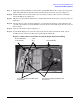
Cabling for the HP 9000 rp3440 Server Configuring the Server Firmware and Software for RAID Step 14. Place the PCI cage back into the system. Note that the RAID cable(s) must be flush against the server chassis as they exit the PCI cage cable channel (see Item 1 in Figure 7-17). Then they must be routed around the chassis side of fan 3 to the hard drive backplane (see Item 2 in Figure 7-17) to avoid crimping. Figure 7-17 RAID Cable Routing Through the PCI Cage Board Cover Step 15.
8 Cabling for the HP Integrity rx2620 and rx2600 Servers This chapter describes how to connect the cables of an HP Smart Array 5302, 5304, or 6402 controller card to the internal hard drives of an HP Integrity rx2620 or rx2600 Server. NOTE These instructions do not apply if you are connecting the controller card to an external mass storage box. Refer instead to the HP Smart Array Controller User Guide that shipped with your card.
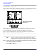
Cabling for the HP Integrity rx2620 and rx2600 Servers Figure 8-1 Smart Array 5302 Controller Card Figure 8-2 Smart Array 5304 Controller Card 76 Chapter 8
Cabling for the HP Integrity rx2620 and rx2600 Servers Figure 8-3 Smart Array 6402 Controller Card Table 8-2 identifies the major components of the Smart Array 6402 controller card.
Cabling for the HP Integrity rx2620 and rx2600 Servers Installing the HP Smart Array Controller Card required for RAID, you need to install cable A7231-63025 as described in the “Recabling for RAID” section later in this chapter. If you opt to use both ports of the Smart Array controller card for your internal drives, you must purchase an additional HP Smart Array controller if you want external RAID mass storage. Installing the HP Smart Array Controller Card Step 1.
Cabling for the HP Integrity rx2620 and rx2600 Servers Recabling for RAID Step 4. Grasp the PCI cage cover and slide it away from the bulkhead end of the PCI cage. Lift the cover off the PCI cage as shown in Figure 8-5. Figure 8-5 Removing the PCI Cage Board Cover Step 5. Install the HP Smart Array controller card in PCI Slot 3 (see Figure 8-6). This is required when connecting the HP Smart Array controller card to the internal hard disk drives.
Cabling for the HP Integrity rx2620 and rx2600 Servers Recabling for RAID Figure 8-7 Default Cabling for Internal Hard Drives B A Figure 8-8 Physical Drive Location (front of server) B A 2 1 0 Your server's internal hard disk drives can be set up for single or dual channel RAID support. To use RAID with your server's internal hard disk drives, you must disconnect the internal SCSI cable(s) from their controller and the hard disk drive backplane (described below) and remove them from the system.
Cabling for the HP Integrity rx2620 and rx2600 Servers Recabling for RAID Step 2. To remove a fan, grasp the fan module with your index finger and thumb and lift it out of its slot. Note that each of the modules has indentations for grasping them with your index finger and thumb. See Figure 8-10. Figure 8-10 Removing the Fans Step 3. To remove a SCSI cable, lift up on the fan power bridge as shown in Figure 8-11. Figure 8-11 Lifting the Fan Power Bridge Step 4.
Cabling for the HP Integrity rx2620 and rx2600 Servers Recabling for RAID Step 6. Use a T-15 torx driver to unscrew the two power connector mounting screws and remove the power connectors from the back of the system. See Figure 8-12. Figure 8-12 Removing the Power Connectors Step 7. Disconnect the iLO Manageability card connector (orange) as shown in Figure 8-13. Figure 8-13Disconnecting the iLO Manageability Card Connector Step 8.
Cabling for the HP Integrity rx2620 and rx2600 Servers Recabling for RAID Step 11. Disconnect and remove any unused SCSI cables from the system board, as shown in Figure 8-15. Figure 8-15 Disconnecting and Removing Unused SCSI Cables from System Board Step 12. Do one of the following, depending on whether you are configuring for single or dual channel support: a.
Cabling for the HP Integrity rx2620 and rx2600 Servers Recabling for RAID Figure 8-16 Single Channel RAID Cabling from a Controller Card Installed in the PCI Cage Figure 8-17 Dual Channel RAID Cabling from a Controller Card Installed in the PCI Cage Step 13. Replace the PCI cage board cover, routing the RAID cable out of the cover's cable channel (see Figure 8-18).
Cabling for the HP Integrity rx2620 and rx2600 Servers Configuring the Server Firmware and Software for RAID Figure 8-19 RAID Cable Routing Through the PCI Cage Board Cover Step 15. Connect the free end(s) of the RAID cable(s) from the controller card to the backplane. The cable connectors are marked. Step 16. Reinstall the iLO Manageability Card and power supply connectors. Step 17. Reinstall any DIMMs that were removed back into their memory banks. Step 18. Lower the fan power bridge. Step 19.
Cabling for the HP Integrity rx2620 and rx2600 Servers Configuring the Server Firmware and Software for RAID 86 Chapter 8
9 Cabling for the HP Integrity rx1620 Server This chapter describes how to connect the cables of an HP Smart Array 6402 controller card to the internal hard drives of an HP Integrity rx1620 Server. NOTE These instructions do not apply if you are connecting the controller card to an external mass storage box. Refer instead to the HP Smart Array Controller User Guide that shipped with your card. The Smart Array 6400 series of controller cards includes two models: the 6402 and the 6404.
Cabling for the HP Integrity rx1620 Server Table 9-2 identifies the major components of the Smart Array 6402 controller card. Table 9-2 SA 6402 Controller Card Components Item ID Description 1 Internal SCSI connector, port A1* 2 Internal SCSI connector, port A2* 3 External SCSI connector, port A1* 4 External SCSI connector, port A2* 5 Controller battery 6 Battery-backed cache module 7 Connector for expansion board * NOTE: Do not use both connectors on a port simultaneously.
Cabling for the HP Integrity rx1620 Server Installing the HP Smart Array 6402 Controller Card Installing the HP Smart Array 6402 Controller Card In this procedure, the existing SCSI cable connected to the Channel A connector on the system board is relocated to the Channel A connector on the Smart Array controller card installed in slot 1 (full-length slot) of the PCI cage.
Cabling for the HP Integrity rx1620 Server Installing the HP Smart Array 6402 Controller Card Figure 9-3 Cable Routing on Smart Array Card and PCI Cage Under slot 2 connector Exit parallel to connector Around heatsink Channel A1 Step 8. Attach the SCSI Channel A connector (previously removed from the system board connector) to the A1 Channel of the controller card. Step 9. Route the SCSI cable around the heatsink on the controller card and under the edge of the PCI slot 2 connector. See Figure 9-3.
Cabling for the HP Integrity rx1620 Server Installing the HP Smart Array 6402 Controller Card Figure 9-5 Cable Routing at SCSI Cage Do not block fans Route over IDE cable (if present) Step 15. Complete the installation by following the instructions provided in the HP Integrity rx1600 Operation and Maintenance Guide for closing up the server, installing it in a rack, and powering it up. To enable RAID, refer to the controller card documentation.
Cabling for the HP Integrity rx1620 Server Installing the HP Smart Array 6402 Controller Card 92 Chapter 9